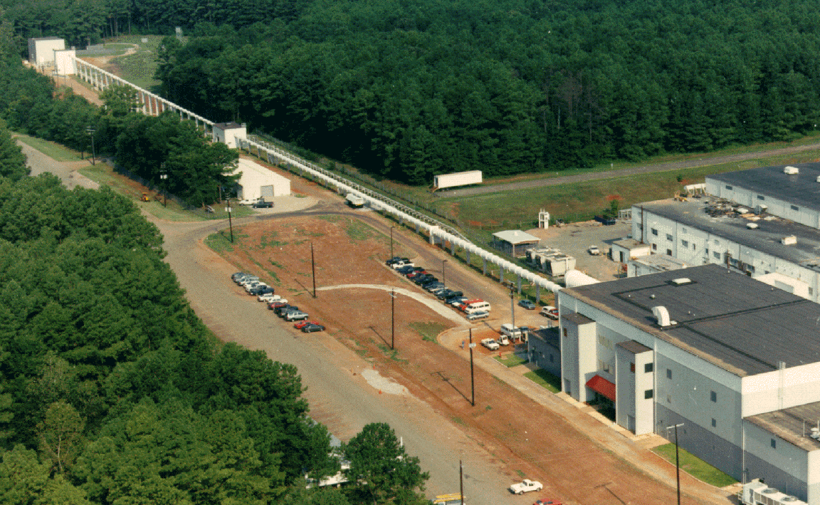
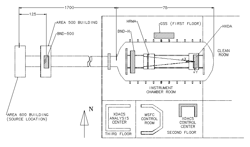
Figure 2 and Figure 3 show a photograph and sketch, respectively, of the XRCF. The XRCF is at the MSFC and consists of the X-ray source system located 1700 feet from a 75' x 15' x 15' instrument chamber housed within a three story control building. X-rays generated by the source travel through a vacuum pipe to the instrument chamber where the HRMA, gratings, and the focal-plane instruments will be located. Along the X-ray pipe, the BND-500 is located about 125 feet away from the X-ray source. The BND-H is located around the HRMA entrance. The test control center is on the 2nd floor of the control building, and a data analysis center is on the 3rd floor.
At the XRCF, the coordinate system is defined such that the positive x-direction is from the instrument chamber to the source, and the positive z-direction is towards the zenith. The HRMA will be on a mount that can provide an angular change of the mirror axis relative to the facility optical axis (x-axis). The HRMA will be gravitationally off-loaded to minimize gravitational effects. Due to the finite source size and source distance at the XRCF, the X-ray beam will be brought to focus at about 190 mm behind the in-flight position. Special hardware has been constructed to position the gratings and the focal-plane instruments at their appropriate locations.
For Phase Zero and Phase One calibration, the focal-plane instruments are the HXDA, part of the HXDS. The HXDA has two Flow Proportional Counters (FPCs), one Solid State Detector (SSD), and a High Speed Imager (HSI). An aperture plate with a suite of circular apertures and slits will be placed in front of the FPC, and a similar aperture will be in place for the SSD. The HXDA has translation capability in all three directions, but no rotation.
For Phase Two, the science instruments will be at the focal plane. According to the current plan, ACIS and HRC will be integrated on the Science Instrument Module (SIM), which can move along x- and z- directions (see The Systems of the AXAF Observatory in issue 2 of this Newsletter). At the XRCF, the SIM will be mounted on a Five Axis Mount (FAM) which is specially constructed for the XRCF calibration to provide alignment flexibility.
