| PREVIOUS | INDEX | NEXT |
| Description | Requirement | Actual |
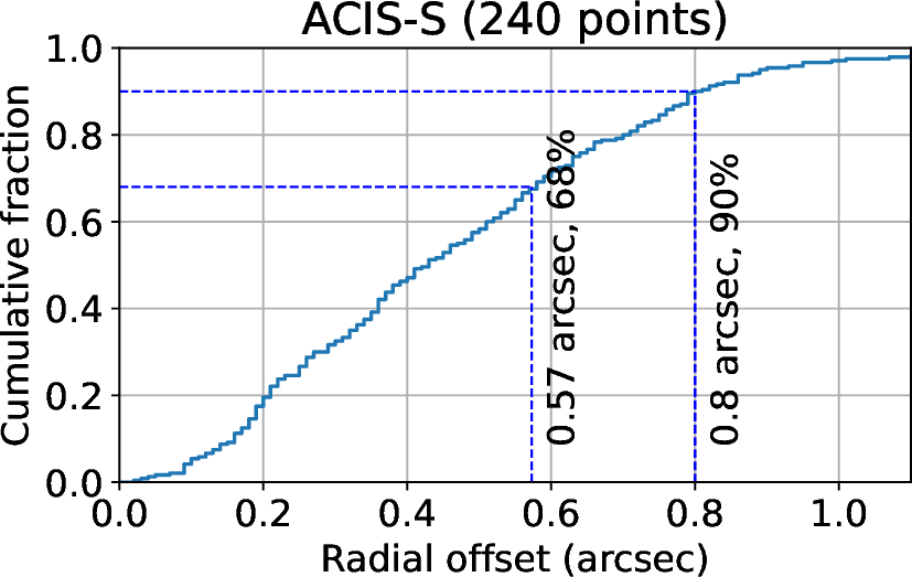
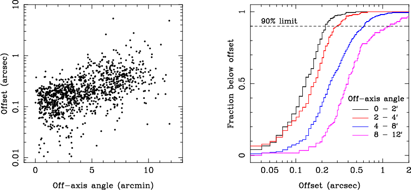
| Celestial location | 1.0 arcsec (RMS radius) | 0.57 arcsec |
| Image reconstruction | 0.5 arcsec (RMS diameter) | 0.39 arcsec |
| Absolute celestial pointing | 30.0 arcsec (99.0%, radial) | 8 arcsec |
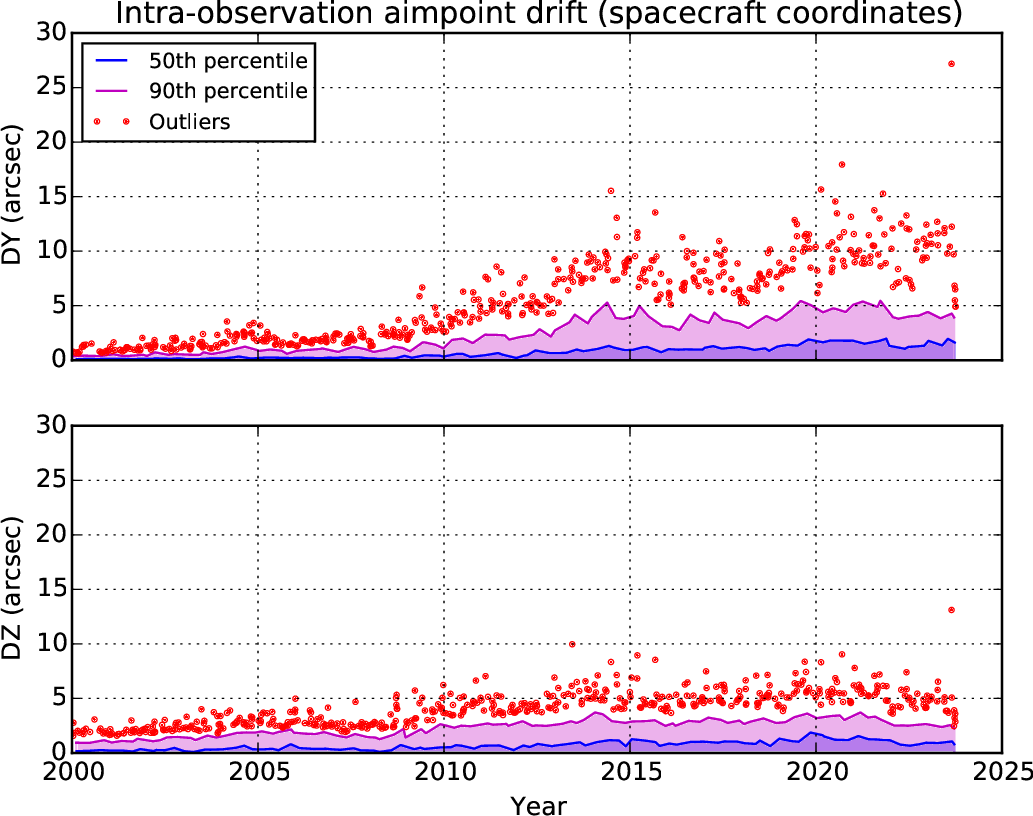
| PCAD 10 sec pointing stability | 0.12 arcsec (95% RMS) | 0.12 arcsec (pitch) |
| 0.09 arcsec (yaw) |
| Catalog Star Magnitude | Acquisition Success | Tracking Success |
| All stars | 94% | 99% |
| 10.0 - 10.3 mag stars | 78% | 90% |
| 10.3 - 10.9 mag stars | 72% | - |
| Mode | Sensors | Control | Description |
| Standby | - | - | OBC commands to RWA, RCS, and Solar Array Drive Assembly (SADA) disabled, for initial deployment, subsystem checkout, etc. |
| Normal Pointing | IRU, ACA | RWA | Point at science target, with optional dither |
| Normal Maneuver | IRU | RWA | Slew between targets at peak rate of 2° per minute |
| Normal Sun | IRU, CSS, FSS | RWA | Acquire the Sun and hold spacecraft −Z axis and solar arrays to the Sun |
| Safe Sun | IRU, CSS, FSS | RWA | Safe mode: acquire the Sun and hold spacecraft −Z axis and solar arrays to the Sun |
| Derived Rate Safe Sun | IRU, CSS, FSS | RWA | Similar to Safe Sun Mode, but using only one gyro (two axes) plus Sun sensor data |
| Transfer orbit only - now disabled | |||
| Powered Flight | IRU | RCS | Control Chandra during Liquid Apogee Engine burns |
| RCS Maneuver | IRU | RCS | Control Chandra using the RCS |
| RCS Safe Sun | IRU, CSS, FSS | RCS | Same as Safe Sun Mode, but using RCS instead of RWA for control |
| Parameter | HRC | ACIS |
| Phase (pitch) | 0.0 rad | 0.0 rad |
| Phase (yaw) | 0.0 rad | 0.0 rad |
| Amplitude (pitch) | 20.0 arcsec | 16.0 arcsec |
| Amplitude (yaw) | 20.0 arcsec | 16.0 arcsec |
| Period (pitch) | 768.6 sec | 2000.0 sec |
| Period (yaw) | 1087.0 sec | 1414.0 sec |
|
|
| Product | Description |
| ASPSOL | Final aspect solution with errors |
| ASPQUAL | Aspect solution quality indicators |
| AIPROPS | Aspect Intervals |
| ACACAL | ACA calibration data from the optical database (ODB) and CALDB |
| GSPROPS | Guide star properties, both from the AXAF Guide and Acquisition Star Catalog and as actually observed with the ACA |
| FIDPROPS | Fiducial light properties, as commanded and as observed |
| ACADATA | Aspect camera telemetry (including ACA housekeeping) and images after CCD-level correction |
| ACACENT | Image centroids and associated fit statistics |
| GYROCAL | Gyro calibration data from ODB and CALDB |
| GYRODATA | Gyro raw data and gap-filled, filtered data |
| KALMAN | Intermediate and final data in Kalman filter and smoother |
| PREVIOUS | INDEX | NEXT |