
|
|
|
Further information is available at
LETG/HRC-S Background Filtering and links therein.
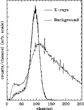
Significant background reduction in LETG/HRC-S spectra, of roughly 50 to 70% depending on wavelength, with x-ray losses of less than 1%, is made possible by the HRC-S's energy resolution, which is approximately 20% FWHM locally for monochromatic radiation. The plot below compares the pulse-height distribution for x-rays and background over areas on the HRC-S having nearly the same gain, specifically, having a mean pulse height of PHA=90 for Al-K radiation during lab calibration. As can be seen, one can put fairly tight limits on PHA values to eliminate background while not throwing away many x-ray events. The main x-ray peak is well fit by a Gaussian, with a smaller peak around PH=20-30. It is not yet clear if this secondary peak is part of the "true" PHA spectrum or perhaps due to anomalous behavior in the HRC electronics (discussed in the presentation on Miscellaneous HRC-S Mysteries).
To take full advantage of the difference between x-ray and background PHA distributions, however, we must correct for gain variations across the HRC-S.
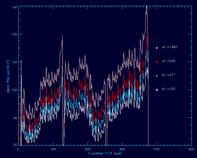
Gain varies by more than a factor of two across the detector, but the variations are very repeatable, as shown above. The four curves are from lab calibration data obtained at four different energies on the central detector segment.
Those curves also show the energy dependence of the mean PHA value. The relationship between PHA and energy follows a simple log-linear line, allowing us to determine the mean PHA at any energy.
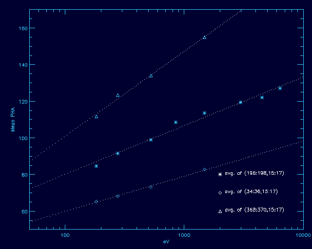
The three curves correspond to three locations on the HRC-S with high, medium, and low gains.
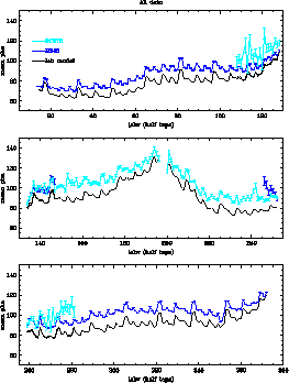
Flight gain in the HRC-S is similar to the lab gain, allowing us to apply the lab calibration with only a few modifications (primarily a 14% overall increase in gain) to flight data. As can be seen, the mean PHA values for flight and lab data track very well.
The 14% general increase does not apply perfectly. Areas of high gain show less of an increase in mean PHA than areas with low gain. Various empirical tweaks were made to obtain better agreement between flight data and the model based on lab data.
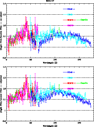
The top panel compares flight and lab mean PHA values from the positive and negative orders of 3C273 (a hard source with substantial hard-to-model effects from higher orders) and HZ43 (a soft source with mininal higher order contamination). The bottom panel shows the flight/model PHA ratios after adjusting the lab results. Note that the range of ratios is smaller and that the light and blue curves (from negative and positive orders) agree better. The range between 30 and 70 Angstroms should be ignored--higher orders and background make the results suspect. Results from Capella (in green) are much more reliable because of their better S/N. (Post-presentation notes: PKS2155 is better than 3C273 because less higher-order contamination. RXJ1856 can be used at intermediate wavelengths.)
After adjusting the lab results, there is an overall difference of about 14% between flight and model results (although somewhat less at wavelengths beyond about 130 Ang). The HRC-S gain map is normalized so that 1 keV photons produce a PI (Pulse Invariant) mean value of 128 everywhere on the detector.
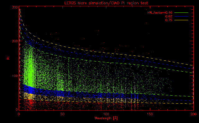
Below is a MARX model of mean PI vs wavelength. The simulation is not very good, with uniformly low PI estimates, but it's a nicely colored plot that shows how the PI limits are applied. Sequentially tighter filters correspond to "light", "medium," and "heavy" filtering. The slight kink near 130 Ang reflects the lower flight/model ratio seen in the previous plot.
The plots below, for negative and positive orders, show the number of counts per HRC pixel (integrated in the cross-dispersion direction) in the background extraction region for a sample observation. The top curve is for no filtering at all, the next (pink) is for when events with PHA=255 are excluded (not generally recommended because of its slightly less uniform effect on background reduction), and the lowest three are for light, medium, and heavy PI filtering.
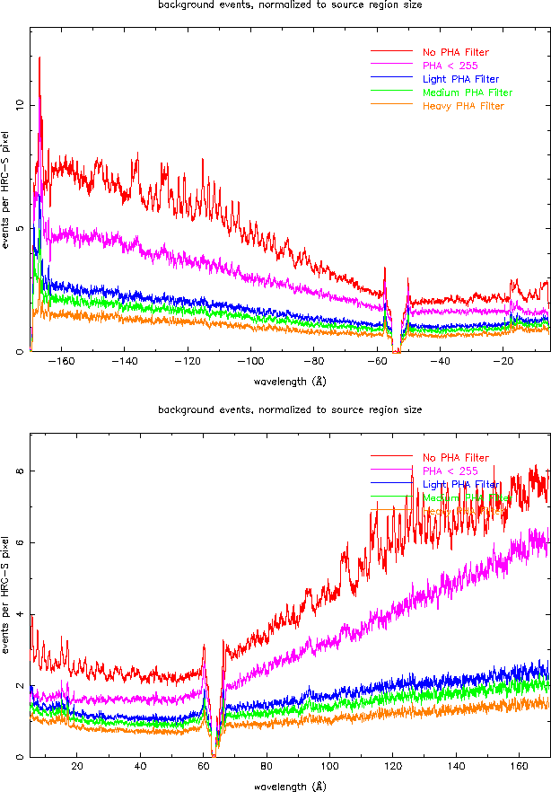
Light filtering removes 50-70% of the background with <1% x-ray loss. Medium removes 55-75%/2%, and heavy removes another 5% of the background but with varying effect on x-ray events. We recommend using light PI filtering as the default.
PI filtering is currently not part of standard Pipeline processing, although there are plans to include light filtering in the near future. Status-Bit filtering IS part of the Pipeline, however, and removes roughly 1% of x-ray events, although virtually all those events are in some sense "bad." The meaning of "bad" will be discussed in more detail in the presentation on Miscellaneous HRC-S Mysteries).
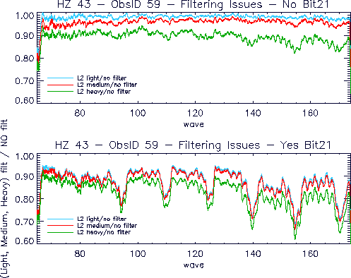
The plot below (top panel) shows the net x-ray loss for combined Status-Bit and PI filtering. The bottom panel shows the effect of filtering on status-bit #21. This problem was discovered in May 2001 and has been corrected in all subsequently processed data. The cause was the application of HRC-I filtering parameters to the HRC-S. In principle, the same parameters should work for both detectors, but the HRC-S is in generall less well behaved than the HRC-I, which complicates its calibration.
Note, when comparing the top and bottom panels, that the same sort of pathological behavior that causes the bit#21 problem also appears, less strongly, in the heavy PI filter.
Last modified: 12/11/06
|
The Chandra X-Ray
Center (CXC) is operated for NASA by the Smithsonian Astrophysical Observatory. 60 Garden Street, Cambridge, MA 02138 USA. Email: cxcweb@head.cfa.harvard.edu Smithsonian Institution, Copyright © 1998-2004. All rights reserved. |