

How can I define a region around a single chip?
It is often desireable to define a region in sky coordinates that covers a single ACIS CCD (the "Why filter on sky coordinates" FAQ entry contains several reasons why this is useful).
The regions can be created with the skyfov tool. This tool is used to create the sky field of view (FOV) file included in the standard data distribution for observations processed with ASCDSVER 6.9.0 or later; these files have names like acisf03519_000N001_fov1.fits.
The skyfov tool requires the event file and, optionally, the aspect solution and mask file of the observation. It creates a region file which contains a polygon describing each chip. In the example below we show how it can be used with the aspect solution; see the help file for further information on the tool.
unix% punlearn skyfov
unix% skyfov acisf00578N002_evt2.fits chips.reg aspect=pcadf052378346N002_asol1.fits
The output file - in this example chips.reg, but the *fov1.fits also follow the same format - is a FITS-format region file with columns that look like:
unix% dmlist chips.reg cols

--------------------------------------------------------------------------------
Columns for Table Block FOV
--------------------------------------------------------------------------------

ColNo  Name                 Unit        Type             Range
   1   POS(X,Y)[5]          pixel        Real8(5)       -Inf:+Inf            Position
   2   SHAPE                             String[16]                          Region shape type
   3   R[2]                 pixel        Real8(2)       -Inf:+Inf            Radius
   4   ROTANG[2]            pixel        Real8(2)       -Inf:+Inf            Angle
   5   COMPONENT                         Int2           -                    Component number
   6   CCD_ID                            Int2           -                    CCD ID

--------------------------------------------------------------------------------
World Coord Transforms for Columns in Table Block FOV
--------------------------------------------------------------------------------

ColNo    Name
1:    EQPOS(RA ) = (+212.8339)[degree] +TAN[(-0.000136667)* (POS(X)-(+4096.50))]
           (DEC)   (+52.2005 )              (+0.000136667)  (   (Y) (+4096.50))
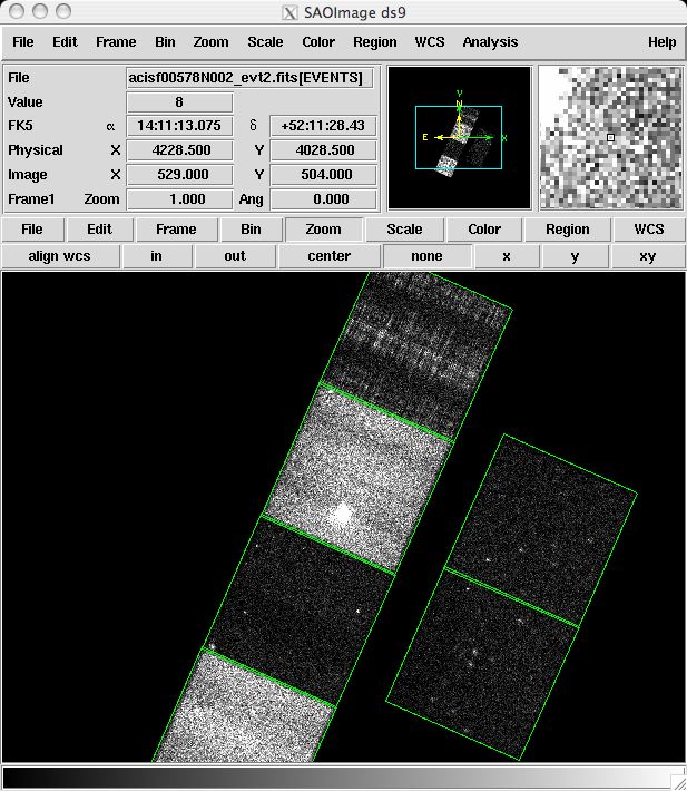
This FOV file can be viewed in ds9 (the "[fov]" is needed to tell ds9 which block of the file the region information is stored):
unix% ds9 acisf00578N002_evt2.fits -region "chips.reg[fov]"
which produces this image, and it can be used to filter files; for instance to select only those events in the S3 or S1 and S3 chips:
unix% dmcopy "acisf00578N002_evt2.fits[sky=region(chips.reg[ccd_id=7])]" ccd_s3.fits
unix% dmcopy "acisf00578N002_evt2.fits[sky=region(chips.reg[ccd_id=5,7])]" ccd_s13.fits
Alternative ways of creating region files for particular CCDs include:
- Using ds9
-
DS9 can be used by creating a "rotbox" region around the chip. For chip S3 (ccd_id=7) of ObsID 578, the region would look like:
unix% cat /home/username/rotbox.reg
# Region file format: CIAO version 1.0
rotbox(4208.1133,4374.8595,1058.3076,1068.9058,336.49673)
This method can be a bit frustrating, however, as it involves rotating the shape and deciding by eye where the chip boundaries are.
- Using dmcoords
-
A more sophisticated, though more involved, method combines the CIAO tool dmcoords with Unix utilities:
unix% set roll = `dmkeypar acisf00578N002_evt2.fits ROLL_NOM echo+`
unix% dmcoords acisf00578N002_evt2.fits asolfile="pcadf052378346N002_asol1.fits" \
      chip_id=7 opt=chip chipx=512.5 chipy=512.5\
      verbose=1 | grep "SKY(" | awk 'BEGIN {printf("# Region file format: CIAO version 1.0\nrotbox(")}\
      { printf("%f,%f,1024,1024,%f)\n", $2, $3, 360-'$roll')}' > chip_s3.reg

unix% cat chip_s3.reg
# Region file format: CIAO version 1.0
rotbox(4198.980000,4370.790000,1024,1024,66.148798)
The dmcoords command finds the center of the chip in sky coordinates, then creates a 1024x1024 region that takes the roll angle (found with dmkeypar) into account. Note that the chip_id parameter may need to be changed for your observation.
The regions created by these two methods can be used just like any other ASCII region file:
unix% dmcopy "acisf00578N002_evt2.fits[sky=region(chip_s3.reg)]" filtered_evt2.fits