The "3-tap" position algorithm is used to convert the three amplifier (or tap) signals from an axis into a position relative to the central tap. If QA, QB, and QC are the signals from the three taps, then event position can be approximated by
Xfine = (QC - QA)/(QA + QB + QC).
Unfortunately, the size of the charge cloud can span a range of wires larger than can be collected by the three taps; as a result some information can be lost. The loss of information, in turn, results in the mis-location of the event position when using the simple algorithm given above. The worst case occurs when the event occurs half-way between two taps. In this case two of the three signals will be about equal and the third signal will not be balanced by the signal from a "fourth" tap. The event position will be biased away from the mid-point between the two nearly equal signals toward the center tap. This generates a gap in the image. It should be stressed that these gaps are not caused by a lack of detector response but by the inadequacy of the simple position determination algorithm. Murray and Chappell (1989) have shown that the accuracy of the event position reconstruction can be improved by applying linear or quadratic corrections to the relative position:
Xcorrected = a×Xfine + b×sign(Xfine)×Xfine2
For a more complete description of modeling the HRC CGCD see Murray and Chappell (1989) or "Simulating the Crossed-Grid Charge Detector Response to an Event Charge Cloud".
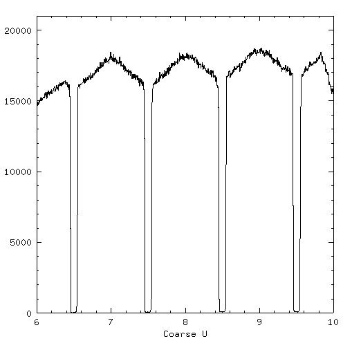
In this projection the gaps at the 1/2 coarse position points are easily seen. A linear degap correction would close the gap by shifting all the calculated positions away from the center of the coarse position by a constant fraction. To the extent that the distribution of events (in the region were there are events) is constant, the linear correction is good. In the figure below the same region as in the previous figure has been degapped using a linear correction (a = 1.055, b = 0.0).
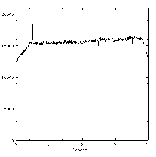
Most of the evidence for gaps has disappeared from this projection. There is a small residual gap between 30 and 31 but this could be removed by choosing a different value for the linear correction around this gap. The linear correction is determined by how far the edge of the distribution must be moved to reach the half-way point between amplifiers.
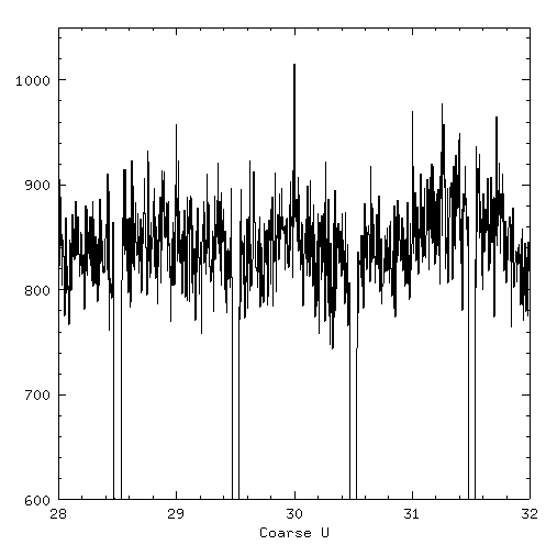
A more difficult situation arises when the distribution of events is not flat. In the above figures there is some suggestion of this across coarse position 30, which peaks toward the center. A more extreme example is shown below in a projection of undegapped data from HRC-S flat field data.
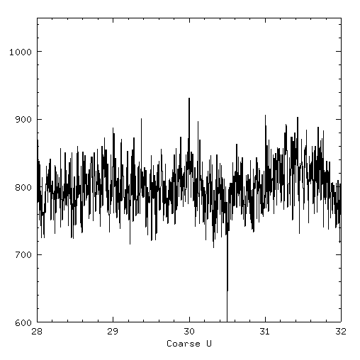
Here the event distribution is not flat over the region in which events are located. The events near the center of the coarse position must be moved a larger fraction away from center than those which are farther out. This can be accomplished using quadratic degapping corrections. The figure below shows this same HRC-S section as previously but this time using a set of fixed quadratic coefficients to degap the data (a = 1.18, b = -0.16).
There are some residual problems at the gaps, both over- and under-correction, but these can be handled by adjusting the coefficients for each coarse position.
Rather than looking for how much "stretch" is required to fill the gap (a linear term), the quadratic coefficients can be found by minimizing the deviation between the positions of the edge of the event distribution and the points which include 1/4, 1/2, and 3/4 of the events from the coarse position center and their expected locations (at 0.5, 0.125, 0.25 and 0.375 respectively). This idea is shown schematically in the following figure. This is similar to the linear "stretch" except that the coefficients are found that do the best job of shifting each of the four points toward the appropriate location.
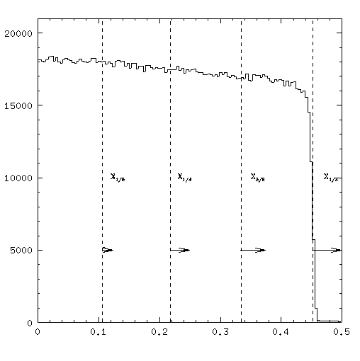
The point labeled X1/8 in this figure should correspond to a value of 1/8 relative to the coarse position. Similarly X1/4, X3/8, and X1/2 should correspond to values of 1/4, 3/8, and 1/2. The minimization can be performed for the "minus" and "plus" side of each coarse position providing a set of position dependent degapping parameters.
Details of the derivation of a specific set of degap parameters are given at the following links.
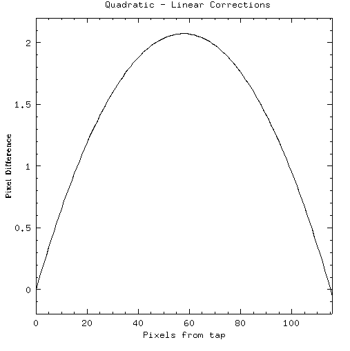
These values reflect the the more extreme values for quadratic degapping coefficients needed for the HRC. The maximum difference between the locations using the two techniques is about 2 pixels. The differences will be even less on the HRC-S V-axis and the HRC-I since the gaps are smaller and the undeppaged histograms show less peaking toward the center.
It may be possible to account for the "non-flatness" of the histograms in the derivation of degapping parameters by using a template for the expected variations rather than assuming a "flat" distribution. This is an area for future work.
Dr. Michael Juda
Harvard-Smithsonian Center for Astrophysics
60 Garden Street, Mail Stop 70
Cambridge, MA 02138, USA
Ph.: (617) 495-7062
Fax: (617) 495-7356
E-mail:
mjuda@cfa.harvard.edu