An Improved AMP_SF Correction Scheme
Introduction
In an earlier memo, I compared two
different schemes for correcting the AMP_SF values on an
event-by-event basis. Both of the methods did a good job on data
from the HRC-I but had problems making good assignments for HRC-S
data. Both methods relied on the expectation that the ratio
between the sum of the signals on the six CGCD taps and the event
pulse-height (PHA) should be close to multiples of 2 once the gain
difference between the amplifiers is taken into account. A higher
level of "noise" on the tap signals of the HRC-S leads to problems
with this assumption. However, revisiting how the range is
selected by the hardware leads to yet another AMP_SF correction
scheme.
New Correction Method
The HRC selects the range setting by comparing the output signal from
the MCPs to a commanded threshold value. The telemetered PHA value
should provide a measure of size of the signal from the MCPs. We
should be able to use the PHA value along with knowledge of the
commanded range-switch level to determine the correct scale
factor. Noise in the relationship between the MCP signal and the
PHA value can lead to an ambiguity in what the appropriate AMP_SF
value is for a given PHA value. We make the assumption that
outside of a specified band around the PHA at the range-switch
points, the AMP_SF value is unambiguous. Within the band around
the range-switch points the AMP_SF value can only be one of the
two surrounding values and the correct one can be selected as the
one that gives an answer that is "closest" to the nominal ratio
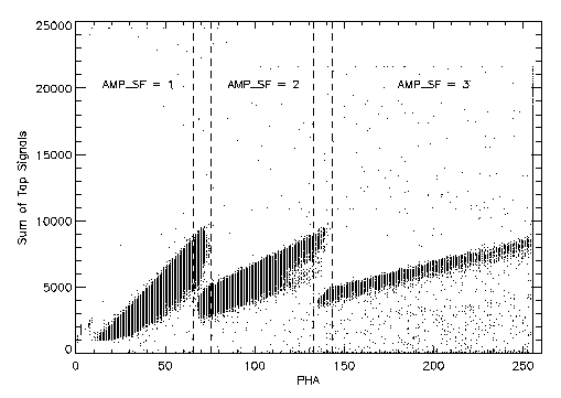
between the sum of the six tap values and the PHA. Figure 1 shows
a schematic representation of this method. The PHA values where
the AMP_SF assignment can be made unambiguously are labeled. Events
with PHA values that are within the two intervals indicated by the
vertical dashed lines require an additional test comparing the sum
of the six tap signals to PHA to select between the two possible
AMP_SF values.

|
|
Figure 1: Sum of Six Tap Values versus PHA - the bands that
define the range-switch regions are indicated by the
dashed lines.
|
PHA values at Range-switch Point
We can examine data to determine the PHA values at the middle of the
range-switching bands. The HRC-I and HRC-S will not necessarily
switch at the same PHA value when commanded with the same
range-switch level. An additional complication with which we must
deal is the fact that the commanded range-switch value has changed
for both the HRC-I and HRC-S from the ones used at the start of the
mission. Table 1 shows the PHA values for the middle of the
range-switch band as observed in data taken on-orbit as a function
of commanded range switch level.
Table 1: PHA of Range-switch Points
| Detector | Range-switch Level | PHA at 1 to
2 | PHA at 2 to 3 |
|---|
| HRC-I | 90 | 50.5 | 99.0 |
| 115 | 64.5 | 126.5 |
| HRC-S | 90 | 51.0 | 99.5 |
| 125 | 70.5 | 137.5 |
Fortunately, the PHA values at the range-switch points appear to be
essentially the same, as a function of commanded range-switch level,
for the HRC-I and HRC-S. The AMP_SF 1 to 2 PHA value is ~0.57× the
commanded range-switch level, while the AMP_SF 2 to 3 PHA value is
~1.10× the commanded range-switch level. For the HRC-I, events
within a band of ±2.0 PHA channels around the values in table 1
require the additional check to determine the correct AMP_SF,
while for the HRC-S the band must be enlarged to ±5.0 PHA
channels.
Check on Sum of Six Taps vs PHA
When the events lie within the bands of PHA values around the
range-switch points an additional check is required to obtain the
best AMP_SF value. Within this band we can use the fact that we
expect the sum of the six tap signals (suitably normalized) to be
the same as the PHA within a factor of two, thus giving the
correct AMP_SF value. For each event that is in the band, the
absolute value of the difference between the sum of the six taps,
scaled by the gain ratio between the taps and the PHA, and the PHA
is calculated for the two relevant AMP_SF values. The AMP_SF value
that produces the smallest difference is then selected.
Algorithm
Here is a pseudo-code fragment of the algorithm described above
# From the event
#   PHA is the event pulse height
#   SUMAMPS is the sum of the 6 CGCD taps (i.e. AU1+AU2+AU3 + AV1+AV2+AV3)
#   AMP_SF re-assigned AMP_SF value
#
# Parameters
#   PHA_1TO2   - middle of the AMP_SF 1 to 2 range-switch band
#   WIDTH_1TO2 - width of the AMP_SF 1 to 2 range-switch band
#   PHA_2TO3   - middle of the AMP_SF 2 to 3 range-switch band
#   WIDTH_2TO3 - width of the AMP_SF 2 to 3 range-switch band
#   GAIN       - relative gain between SUMAMPS and PHA

if (PHA < (PHA_1TO2 - WITDH_1TO2))
   AMP_SF = 1
else if (PHA < (PHA_1TO2 + WITDH_1TO2))
   AMP_SF = 1
   diff1 = abs(PHA - SUMAMPS/GAIN)
   diff2 = abs(PHA - 2*SUMAMPS/GAIN)
   if (diff2 < diff1) AMP_SF = 2
else if (PHA < (PHA_2TO3 - WITDH_2TO3))
   AMP_SF = 2
else if (PHA < (PHA_2TO3 + WITDH_2TO3))
   AMP_SF = 2
   diff2 = abs(PHA - 2*SUMAMPS/GAIN)
   diff3 = abs(PHA - 4*SUMAMPS/GAIN)
   if (diff3 < diff2) AMP_SF = 3
else
   AMP_SF = 3
endif
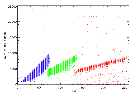
Figure 2 shows the result of applying this method to some HRC-S
data. The points are color-coded based on their assigned AMP_SF
values. There is no evidence for the mis-assignments that were
made by either of the two methods presented in the earlier memos.

|
Figure 2: Sum of Six Tap Values versus PHA color-coded by the
corrected AMP_SF value.
Blue:
AMP_SF=1,
Green: AMP_SF=2,
and
Red: AMP_SF=3.
|
Conclusion
I have devised yet another algorithm for correcting the AMP_SF values
of HRC events. While it is somewhat more complicated, it does a
better job at correcting the AMP_SF values on the HRC-S than
either of the two methods discussed previously. I recommend that
this method be adopted for use in a revised version of
hrc_process_events.
Last modified: Wed Jan 9 11:36:55 EST 2002
Back to my memos page
Michael Juda
email Mike Juda


