TEPHIN Planning Limit Increase to 117° F
Edwin Kellogg
CXC Technical Support Team
Scott Wolk, Takashi Isobe, Brad Spitzbart, Tom Aldcroft and Mike Juda
CXC Science Operations Team
Note: items in green
are recent updates; those in red
with strikethrough are deleted.
Table of Contents
2. The systems identified as of concern by Matt & us 1
2.1.4. Durations above limits 1
2.1.6. Consequences of violating the limits 1
2.1.7. Other considerations regarding increase of the limits 1
2.2.2. Temperature history (°F) 1
2.2.4. Durations above limits 1
2.2.6. Consequences of violating the limits 1
2.2.7. Other considerations regarding increase of the limits 1
2.3.4. Durations above limits 1
2.3.6. Consequences of violating the limits 1
2.3.7. Other considerations regarding increase of the limits 1
2.4. EPHIN Input/Output Electronics (EIO) Housing Temperature (TEIO) 1
2.4.4. Durations above limits 1
2.4.6. Consequences of violating the limits 1
2.4.7. Other considerations regarding increase of the limits 1
2.5.4. Durations above limits 1
2.5.6. Consequences of violating the limits 1
2.5.7. Other considerations regarding increase of the limits 1
2.6. Retroreflector-collimator Assembly(RRCA) 1
2.6.4. Durations above limits 1
2.6.6. Consequences of violating the limits 1
2.6.7. Other considerations regarding increase of the limits 1
2.7. Fiducial Transfer Mirror (FTM) Thermal Shield 1
2.7.4. Durations above limits 2
2.7.6. Consequences of violating the limits 2
2.7.7. Other considerations regarding increase of the limits 2
We are assessing the safety of dwelling at "normal" (e.g., 60 to 130° pitch) sun pitch. After reviewing the data from the last two normal sun events, it looks like a TEPHIN planning limit increase to 117° F is feasible. Matt (Matthew Dahmer mdahmer@ipa.harvard.edu) has identified critical locations of concern.
There is an increased risk that the following sensors will violate their caution high limits:
TEIO EPHIN ELECTRONICS HOUSING TEMP
TFSSBKT1 FSS (Fine Sun Sensor) BRACKET-1 TEMP (+Y)
TFSSBKT2 FSS (Fine Sun Sensor) BRACKET-2 TEMP (+Y)
TSCTSF1 SC-TS FITTING -1 TEMP - Spacecraft strut mount
TSCTSF6 SC-TS FITTING -6 TEMP - Spacecraft strut mount.
The EIO and FSS units heat up the fastest at attitudes slightly off 90°. The spacecraft strut mounts (TSCTSF1/6) heat up the most during swings towards tail sun after long dwells at forward attitudes. All of these units are at or above their P007 limits so further work will need to be done before these limits can be increased. Other sensors that would not be in danger, but should be watched for trends are the aspect camera housing temperatures (AACH1T, AACH2T) and the OBA temperatures/gradients.
What is the history of these temperatures?
See plots below. Below we have attached our current predictive plots for these systems. Most have two plots: vs. time and vs. attitude. Some plots vs. attitude are still missing.
What are their yellow and red limits?
Here is a list, with temperatures in K:
|
MSID |
yel_lo |
yel_hi |
red_lo |
red_hi |
Validity time, sec since 1998.0 |
Description |
Unit |
Source |
|
TEIO |
253.0 |
333.15 |
250.2 |
358.15 |
166319999.0 |
#EPHIN ELECTRONICS HOUSING TEMP |
K |
mta05_01_05(FOT) |
|
TFSSBKT1 |
237.4 |
342.0 |
223.0 |
354.0 |
134783999.0 |
#FSS BRACKET-1 TEMP (+Y) |
K |
mta05_01_05 |
|
TFSSBKT2 |
237.4 |
342.0 |
223.0 |
354.0 |
134783999.0 |
#FSS BRACKET-2 TEMP (+Y) |
K |
mta05_01_05 |
|
TSCTSF1 |
260.8 |
294.1 |
253.0 |
303.0 |
100828799.0 |
#SC-TS FITTING -1 TEMP |
K |
p008 |
|
TSCTSF6 |
255.8 |
300.2 |
253.0 |
303.0 |
100828799.0 |
#SC-TS FITTING -6 TEMP |
K |
p008 |
|
AACH1T |
278.0 |
293.0 |
250.2 |
310.8 |
178761599.0 |
#AC HOUSING TEMP (ACH1) |
K |
mta07_03_03 |
|
AACH2T |
278.0 |
293.0 |
250.2 |
310.8 |
178761599.0 |
#AC HOUSING TEMP (ACH2) |
K |
mta07_03_03 |
|
OOBAGRD3 |
-1.39 |
1.39 |
-1.61 |
1.55 |
100828799.0 |
#RT 505 TO RT 504: PERISCOPE GRADIENT |
K |
p008 |
|
OOBAGRD6 |
-0.27 |
0.27 |
-1.39 |
1.39 |
48815999.0 |
#RT 507 TO RT 506: PERISCOPE GRADIENT |
K |
v6.9 |
|
OHRTHR27 |
296.3 |
298.0 |
280.2 |
308.0 |
100828799.0 |
#RT 20 : PERISCOPE |
K |
p008 |
|
OHRTHR42 |
293.0 |
295.2 |
280.2 |
308.0 |
100828799.0 |
#RT 133: PERISCOPE |
K |
p008 |
|
OHRTHR43 |
292.4 |
294.1 |
280.2 |
308.0 |
100828799.0 |
#RT 134: PERISCOPE |
K |
p008 |
Table 1: Yellow & Red Limits - deg K
Same list, temperatures in F
|
MSID |
yel_lo |
yel_hi |
red_lo |
red_hi |
Validity time, sec since 1998.0 |
Description |
Unit |
Source |
|
TEIO |
-4.27 |
140 |
-9.31 |
185 |
166319999 |
#EPHIN ELECTRONICS HOUSING TEMP |
F |
mta05_01_05(FOT) |
|
TFSSBKT1 |
-32.4 |
155.93 |
-58.3 |
177.53 |
134783999 |
#FSS BRACKET-1 TEMP (+Y) |
F |
mta05_01_05 |
|
TFSSBKT2 |
-32.4 |
155.93 |
-58.3 |
177.53 |
134783999 |
#FSS BRACKET-2 TEMP (+Y) |
F |
mta05_01_05 |
|
TSCTSF1 |
9.77 |
69.71 |
-4.27 |
85.73 |
100828799 |
#SC-TS FITTING -1 TEMP |
F |
p008 |
|
TSCTSF6 |
0.77 |
80.69 |
-4.27 |
85.73 |
100828799 |
#SC-TS FITTING -6 TEMP |
F |
p008 |
|
AACH1T |
40.73 |
67.73 |
-9.31 |
99.77 |
178761599 |
#AC HOUSING TEMP (ACH1) |
F |
mta07_03_03 |
|
AACH2T |
40.73 |
67.73 |
-9.31 |
99.77 |
178761599 |
#AC HOUSING TEMP (ACH2) |
F |
mta07_03_03 |
|
OOBAGRD3 |
-2.5 |
2.502 |
-2.9 |
2.79 |
100828799 |
#RT 505 TO RT 504: PERISCOPE GRADIENT |
F |
p008 |
|
OOBAGRD6 |
-0.49 |
0.486 |
-2.5 |
2.502 |
48815999 |
#RT 507 TO RT 506: PERISCOPE GRADIENT |
F |
v6.9 |
|
OHRTHR27 |
73.67 |
76.73 |
44.69 |
94.73 |
100828799 |
#RT 20 : PERISCOPE |
F |
p008 |
|
OHRTHR42 |
67.73 |
71.69 |
44.69 |
94.73 |
100828799 |
#RT 133: PERISCOPE |
F |
p008 |
|
OHRTHR43 |
66.65 |
69.71 |
44.69 |
94.73 |
100828799 |
#RT 134: PERISCOPE |
F |
p008 |
Table 2: Yellow & Red Limits, deg F
We have a list of systems near their yellow limits: http://asc.harvard.edu/mta_days/mta_envelope_trend/violation_table.html
We are still reviewing this for P009 vs. internal limits.
How long and what are the longest durations they have been above the limits?
There is a summary in the plots below. Specific durations on individual occasions need further analysis.
Why were the limits set as they are?
We need to research the process by which the limits were assigned. We presume that the responsible design engineers at NGST had a major role in setting the limits.
What do we think are the consequences of violating yellow or red limits?
We deal with this question for each MSID separately. See below.
What else should we consider prior to possibly suggesting those limits should be increased?
AACH1T PCAD DEGF 8 AC HOUSING TEMP (ACH1)
AACH2T PCAD DEGF 8 AC HOUSING TEMP (ACH2)
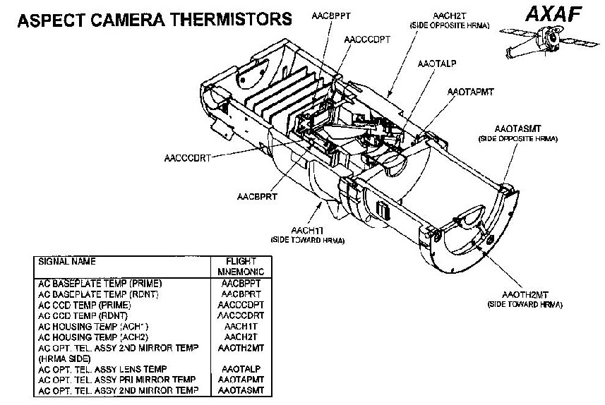
We will be concerned primarily with AACH1T and AACH2T..

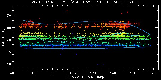

Daily maximum AACH1T AC HOUSING TEMP (ACH1). Colors indicate days since launch.
http://cxc.harvard.edu/mta_days/mta_deriv/F/aach1t_avgPmax.gif
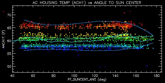

Daily minimum AACH1T AC HOUSING TEMP (ACH1). Colors indicate days since launch.
http://cxc.harvard.edu/mta_days/mta_deriv/F/aach1t_avgPmin.gif
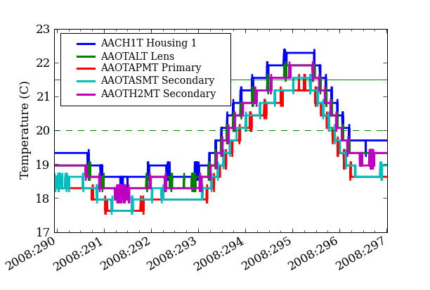
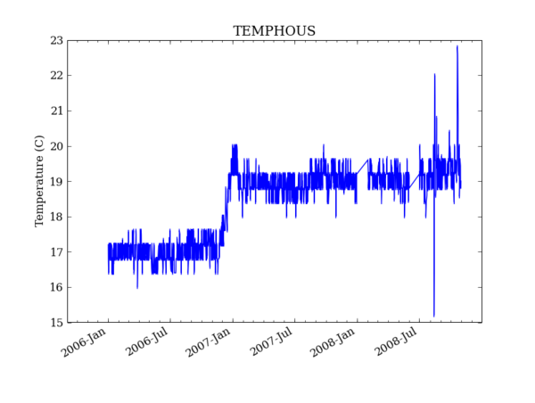
From historical data ACA housing temperatures are generally stable to within about 2° F.
There is a small long term increase due to environmental factors, but the largest influence is heat from the CCD thermoelectric cooler.
The decrease in CCD temperature from 5 to -2° F in late-2006 (increased TEC power) produced a 3.6° F increase in ACA housing temperature.
The ACA is spec'd to meet requirements within the range 14 to 68° F.
The ACA housing temperature yellow high limit is 68° F. (MTA gives 293.0° K, but probably meant 293.15° K).
It was calibrated at Ball up to 70.7° F.
There is at [sic] mention of testing at housing temperatures up to 77° F in the CDA package.
MSID yel_lo yel_hi red_lo red_hi Units
AACH1T 40.73 67.73 -9.31 99.77 °F
The yellow high has been violated on two or three isolated days.
Thermal Performance with a 117° F TEPHIN limit
The normal mission data could be used in conjuction with thermal modeling to predict temperatures for dwells. This modeling effort is now on the table but will take some time.
The most useful predictive data [are?] from the long NSM dwells.
The first of these is less useful because the CCD was not being cooled after the PEA reset. The ACA housing actually got cooler.
Based on discussion with Misty and inspection of LIGER plots for 117° F, the longest dwell at pitches near normal sun would be in the ballpark of ~40 ks (realistically probably less).
Assuming a 40 ks worst case, there is significant risk that the ACA housing temperature will exceed the current yellow limit.
It seems likely that there is margin in the yellow limit and that it can be safely raised (at least from the hardware perspective). Concurrence from Ball etc should be pursued.
From the NSM data the housing settling temperature (infinite dwell) at 90° pitch is less than ~77° F. Therefore there is little risk of exceeding the red limit of 98.6° F.
Image reconstruction with a 117° F TEPHIN limit
Thermal instability during observations can produce alignment shifts that are not corrected by the aspect pipeline. This will result in image reconstruction errors, e.g. a fixed X-ray source appearing to drift in position during the observation. This was seen at the 0.4" level in the first (long grating) observation following the Aug-08 NSM. This was attributed to the periscope gradient getting too large. Given the relatively long timescales it is unlikely that periscope gradients will pose a problem for a TEPHIN limit of 117° F. However for arbitrary dwells at NSM this would certainly be an issue.
Alignment drift
Another area of concern is an alignment drift directly connected to an increase in the housing temperature. When the ACA CCD was cooled to -2.2° F in late 2006 this introduced an absolute celestial location error of about 0.4" in subsequent observations. The exact physical cause of this error is unclear at this time. In any case if the mission attitude profile results in ACA housing temperature swings of 3.6° F or more then we'll need heightened vigilance on aspect image reconstruction and apparent PSF shape.
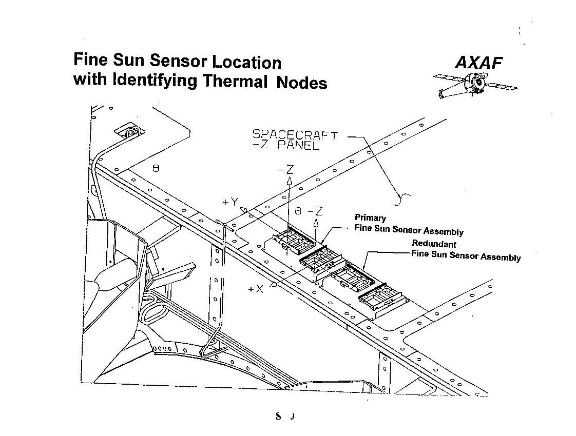
The fine sun sensor is a box located on the outer body of the spacecraft on the –Z side (facing the Sun), perpendicular to the sun line at pitch = 90°.
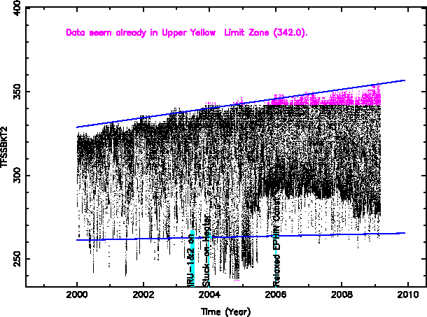
It looks like a simple straight line fit to this is not very meaningful. For the upper fit, a break in year 2005-2006 appears appropriate. The lower temperatures are highly variable, so the line fit is not as useful.
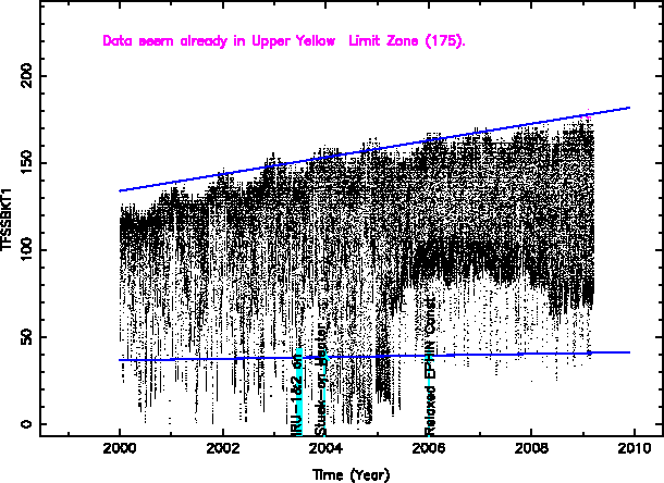
TFSSBKT1 vs. time
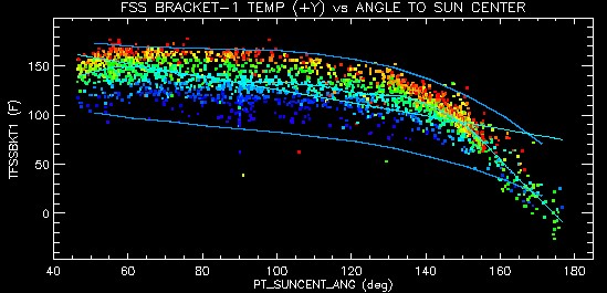

Daily maximum TFSSBKT1 vs.sun pitch angle. Colors are days since launch.
http://cxc.harvard.edu/mta_days/mta_deriv/F/tfssbkt1_avgPmax.gif
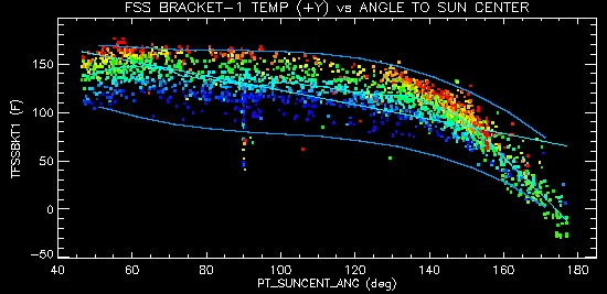

Daily minimum TFSSBKT1 vs.sun pitch angle. Colors are days since launch.
http://cxc.harvard.edu/mta_days/mta_deriv/F/tfssbkt1_avgPmin.gif
TFSSBKT2 THM DEGF 8 FSS BRACKET-2 TEMP (-Y)


Daily maximum TFSSBKT2 vs. sun pitch angle. Colors indicate days since launch.
http://cxc.harvard.edu/mta_days/mta_deriv/F/tfssbkt2_avgAmax.gif
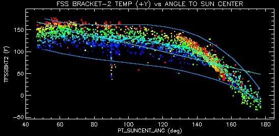

Daily minimum TFSSBKT2 vs. sun pitch angle. Colors indicate days since launch.
http://cxc.harvard.edu/mta_days/mta_deriv/F/tfssbkt2_avgPmin.gif
MSID yel_lo yel_hi red_lo red_hi Units
TFSSBKT1 -32.4 155.93 -58.3 177.53 °F
TFSSBKT2 -32.4 155.93 -58.3 177.53 °F
From the above graph vs. time we see that TFSSBKT2 has been exceeding the upper yellow limit at times since late 2005. It has just about reached the upper red limit at its highest excursions now.
The original concern here was softening of the epoxy degrading the alignment.
Current limits are based on the maximum temperature to which the manufacturer tested a very similar unit (194F)
Unit was not tested to failure
Most susceptible material to heat is an epoxy (ECCOBOND 285) which begins to soften at 221F
Closest sensor is mounted on FSS bracket (TFSSBKT1/2)
Current max bracket temperature is 180.8F
Bracket sensor is approx. 8F cooler than FSS head
Current upper yellow/red limits for the bracket are 181F/186F
Flight Note 413C documents previous work performed on this topic
- draft of presentation to 02 Apr 2009 Flight Directors Board, Matthew Dahmer
We believe epoxy softening was not considered credible below 190° F. It may reach this in late 2010 or 2011. The epoxy may even survive at higher temperatures, considering that 190° F is still well below the standard temperature of boiling water, 212° F.
Should the epoxy soften, an additional force would still be required to change the alignment of the sensor
De-bonding not a concern at these temperatures
The sensor performance would most likely degrade prior to unit failure
The degraded performance could result from higher leakage currents from the solar cells or an alignment shift, as temperatures increase
The errors would increase gradually with temperature, but might stay below Chandra's ability to detect them (on the order of hundredths of degrees of accuracy)
Two new daily plots to be created to monitor FSS performance
FSS pitch vs. commanded solar array angle
Solar array resolver angles vs. commanded solar array angle
[Compare sun angle from aspect solution with solar array readout -EMK]
Should the FSS degrade or fail, continued mission operations would be safe and manageable\
- draft of presentation to 02 Apr 2009 Flight Directors Board, Matthew Dahmer
The epoxy has volatile and nonvolatile constituents. Over time at elevated temperatures in vacuum, the volatile constituents may evaporate, so the epoxy may not soften. Rather, it may be able to withstand higher temperatures until its less volatile constituents decompose into volatile constituents. Perhaps some further temperature testing of the epoxy in vacuum should be done. Testing in air would not be appropriate because in air the epoxy will oxidize, i.e. burn. Another failure that could occur before bulk failure of the epoxy material is at the joint between the epoxy and adjacent material caused by differential thermal expansion. Apparently the epoxy bonds glass parts to metal ones, probably with quite different thermal expansion coefficients. As the temperature goes up, stress may build up in the joint until it exceeds the adhesion limit of the bond.
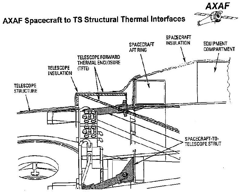
The shaded parts in the drawing contain the TSCTSF1 or TSCTSF6 fittings and the spacecraft-to-telescope struts. The fittings are the attachments between the spacecraft aft ring and the struts.
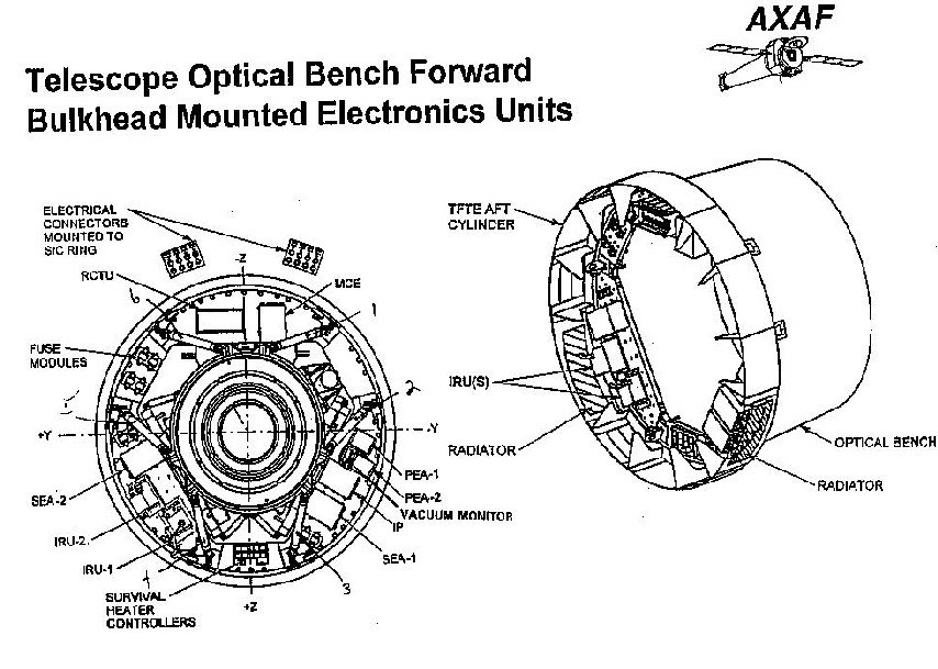
The drawing below shows the azimuthal location of the struts. The location of TSCTSF1 and TSCTSF6 are marked with handwritten numbers. They are those that face the sun, i.e. closest to the –Z axis.
Heat up the most during transitions to hard tail sun attitudes after extended dwells spent at forward sun
Forward sun dwells heat up the central cylinder, where the spacecraft strut mounts (i.e. spacecraft strut fittings) are attached
Tail sun dwells heat the mounts directly
TEPHIN limit increases will allow longer forward sun dwells which could further heat the spacecraft strut mounts
-Z Strut Mount Sensors, TSCTSF1/6, exceeded yellow limits several times within the last six months
Max temperature to date is 81.3F
Existing strut mount upper limits match original P007 database values (factory set values)
Red: 86F
Yellow: 81F
Based on West Coast/ITT comments, sufficient margin exists allowing an increase to existing limits
- draft of presentation to 02 Apr 2009 Flight Directors Board, Matthew Dahmer
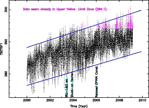
TSCTSF1 THM DEGF 8 SC-TS FITTING -1 TEMP
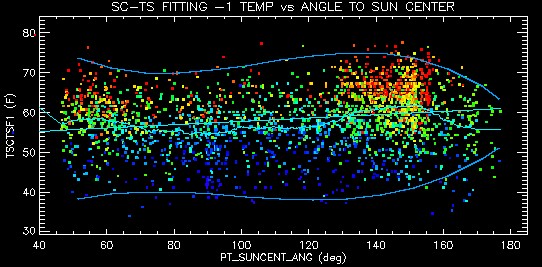

Daily maximum TSCTSF1 versus sun pitch angle. Colors indicate days since launch.
http://cxc.harvard.edu/mta_days/mta_deriv/F/tsctsf1_avgPmax.gif
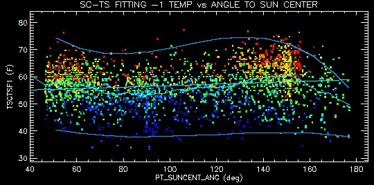

Daily minimum TSCTSF1 versus sun pitch angle. Colors indicate days since launch.
http://cxc.harvard.edu/mta_days/mta_deriv/F/tsctsf1_avgPmin.gif
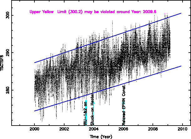
TSCTSF6 THM DEGF 8 SC-TS FITTING -6 TEMP
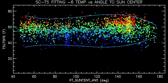

Daily maximum TSCTSF6 versus sun pitch angle. Colors indicate time.
http://cxc.harvard.edu/mta_days/mta_deriv/F/tsctsf6_avgPmax.gif
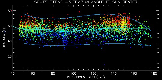

Daily minimum TSCTSF6 versus sun pitch angle. Colors indicate time
http://cxc.harvard.edu/mta_days/mta_deriv/F/tsctsf6_avgPmin.gif
MSID yel_lo yel_hi red_lo red_hi Units
TSCTSF1 9.77 69.71 -4.27 85.73 °F
TSCTSF6 0.77 80.69 -4.27 85.73 °F
TSCTSF1 has been violating yellow high limits since 2005, but has not exceeded red high limits.
Quote from Perry Knollenberg (Mar 4 2009):
The following primary considerations defined the MAX temperature limits of the six SC-TS strut fittings are based on two primary concerns:
Structural integrity:
MAX temperature at launch: structure could tolerate up to +160F
MAX temperature during Shuttle (abort) re-entry: structure could tolerate up to +160F
MAX temperature on-orbit for long-term structural integrity: structures can tolerate up to +230F
Performance during science mission for TS alignment and pointing (TS budget allocation):
MAX temperature (of any or all struts): -4F to +86F
MAX temperature-gradient: -4F to +86F
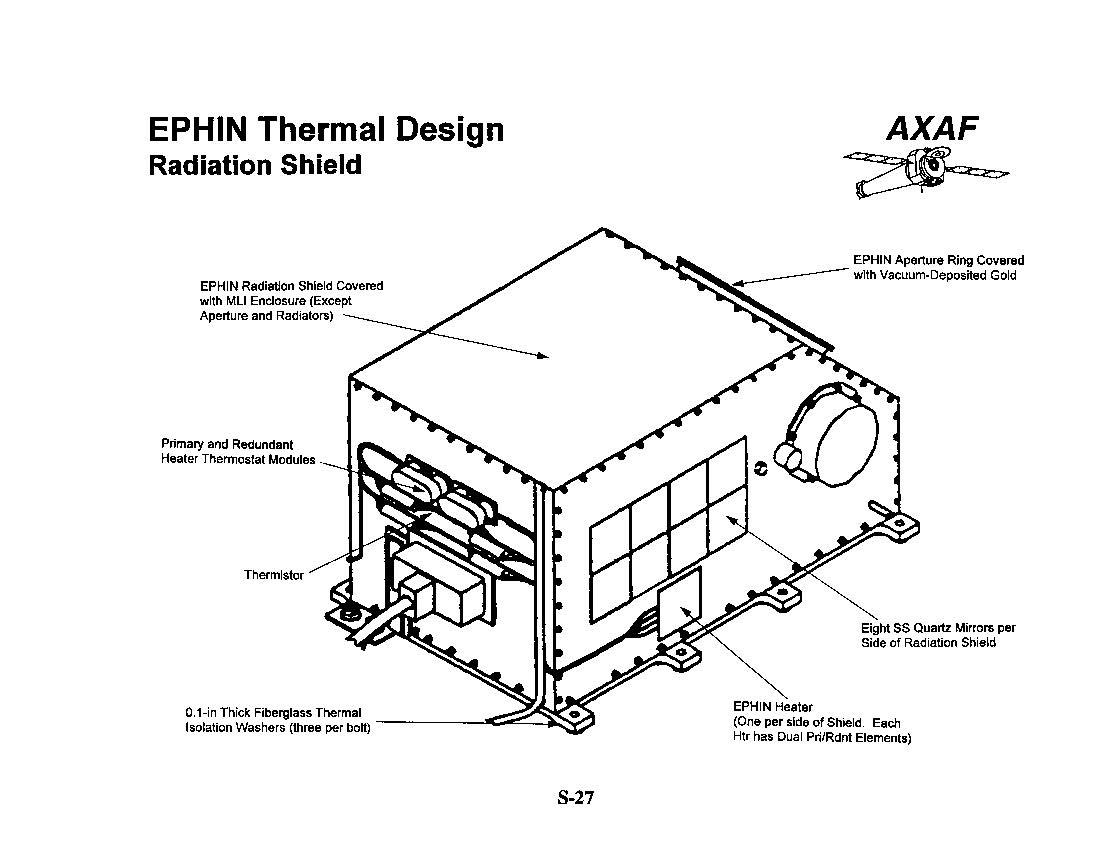

The CDA (1996) refers to series thermostats on the +X side of the EIO. Tom gave a hand drawing from Tan indicating this as well.
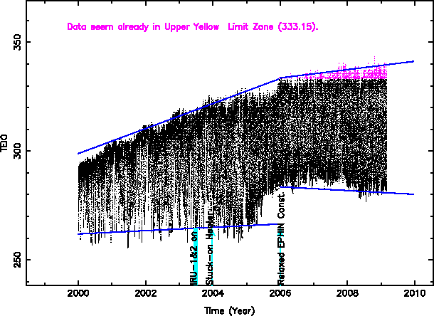
The first figure below shows the daily range of observed temperatures. The maximum values are typically suppressed due to the TEPHIN planning constraint while the minimums are all determined by the amount of time spent cooling in order to satisfy thermal constraints.
The behavior is different since we relaxed the EPHIN constraint at the beginning of 2006. Not only is the rate of T increase less, but the low Ts are not as low, probably because it’s not necessary to cool as aggressively since then.
This plot is of TEIO vs. sun pitch angle, coded by time. The general trend is cooler for larger sun pitch angles.
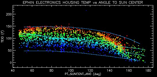

Daily maximum TEIO versus sun pitch angle. Colors indicate time.
http://cxc.harvard.edu/mta_days/mta_deriv/F/teio_avgPmax.gif
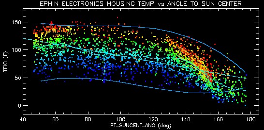

Daily minimum TEIO versus sun pitch angle. Colors indicate time.
http://cxc.harvard.edu/mta_days/mta_deriv/F/teio_avgPmin.gif
|
MSID |
yel_lo |
yel_hi |
red_lo |
red_hi |
Units |
Source |
|
TEIO |
253.0 |
333.15 |
250.2 |
358.15 |
° K |
mta05_01_05(FOT), converted to deg F by EMK |
|
68.0 |
140.27 |
-09.0 |
185.27 |
° F |
||
|
Launch |
|
117 |
|
122 |
° F |
(From MJ) p009 |
|
Revised |
|
160 |
|
185 |
° F |
TEIO has yet to exceed the 160° F yellow limit. It came close during the 2008 October IU Reset induced Normal-Sun episode reaching a maximum of ~158.5° F.
No hardware failure is expected for TEIO below 142° F. We have a 87.8° F minimum margin on the EIO components at this temperature which leads to the higher yellow/red limits.
Flight Note #430 from 07/22/2004 documents the thermal issues with the EIO and Ball's responses to questions.
We could have circuit performance drift at higher temperatures that would probably affect timing signals, rendering the EPHIN data unusable. This would likely cause a RADMON trigger due to "IEPHIN failure".In the near-term increasing the TEPHIN limit as high as 125° F would not be likely to lead to a TEIO much higher than was seen during the NSM episode as the TEIO = 158.5° F came with TEPHIN = 133.9° F.
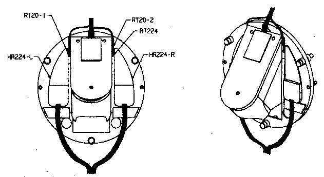
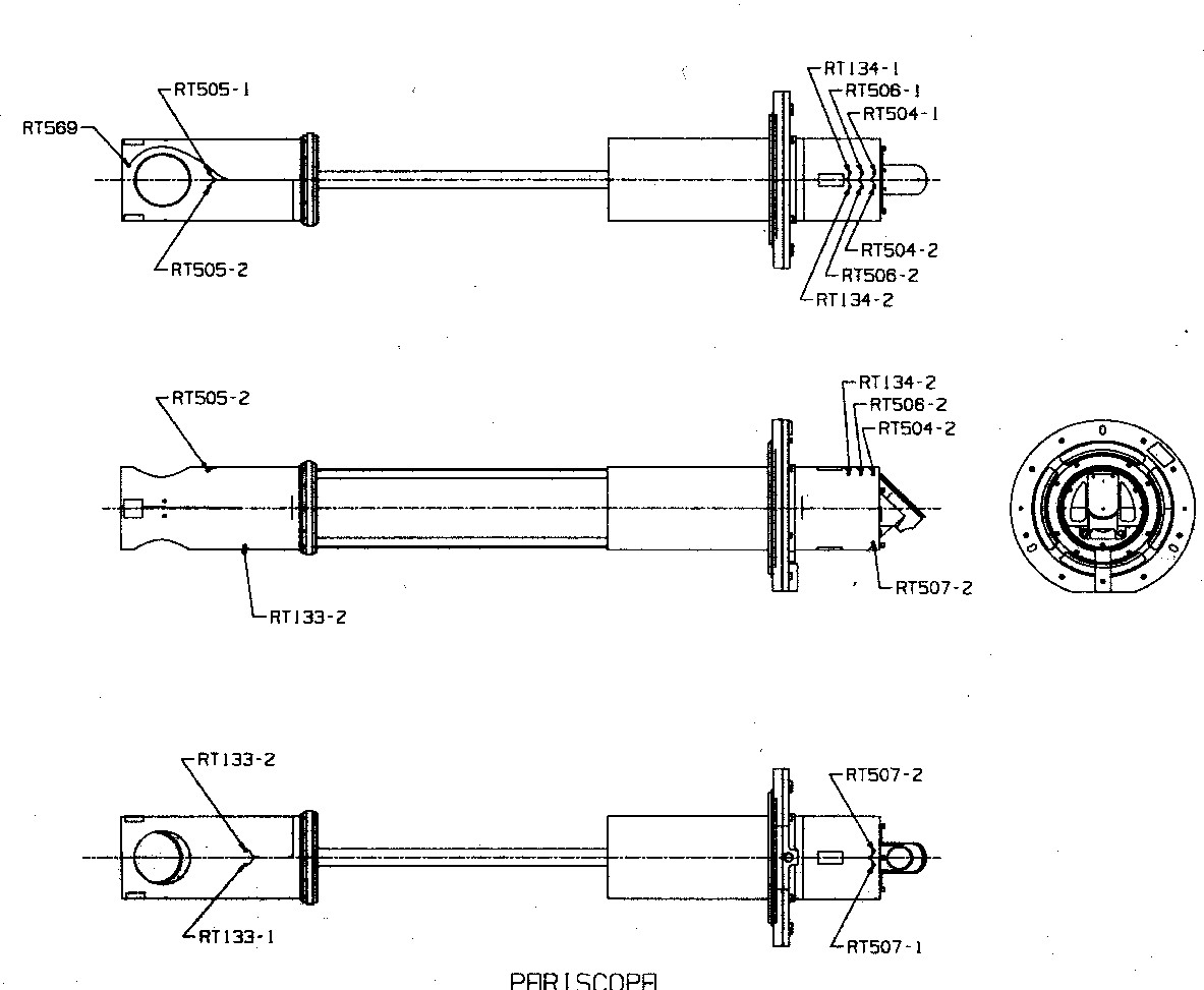
The periscope, or Fiducial Transfer system, FTS, is located on the back end of the HRMA on the same azimuth as the Aspect Camera. In the drawing below, the mounting flange attached to the outside of the HRMA is on the right. The mirror near RT505 on the left protrudes in to the HRMA axis and receives light that originates from the focal plane fiducials and passes through the Retroreflector/Collimator Assembly (RRCA). The periscope mirrors transfer that beam of light to the outside of the HRMA, near RT504 and send it into the Aspect Camera.
Here are the correspondences between thermistor labels and MSIDs:
|
Thermistor |
MSID |
|
RT133 |
OHRTHR42 |
|
RT134 |
OHRTHR43 |
|
RT504, RT505 |
OOBAGRD3 |
|
RT506, RT507 |
OOBAGRD6 |
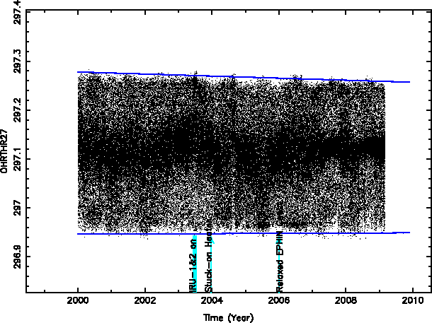
OHRTHR27 RT 20 : PERISCOPE
This monitor point is quite stable, as expected, since it is controlled by the HRMA thermal control system. As long as that system stays in control, the periscope should remain stable.
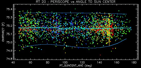

Daily maximum ORTHR27 versus sun pitch angle. Colors indicate time.
http://cxc.harvard.edu/mta_days/mta_deriv/F/ohrthr27_avgPmax.gif
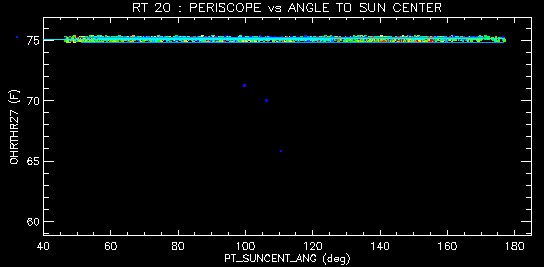

Daily minimum ORTHR27 versus sun pitch angle. Colors indicate time.
http://cxc.harvard.edu/mta_days/mta_deriv/F/ohrthr27_avgPmin.gif
OHRTHR42 RT 133: PERISCOPE
This system has only changed by ~0.18° F.
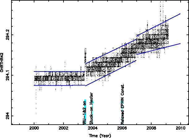
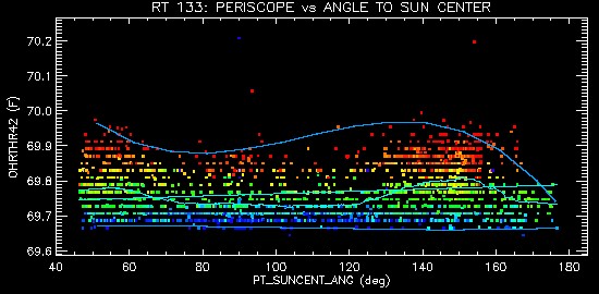

Daily maximum ORTHR42 versus sun pitch angle. Colors indicate time.
http://cxc.harvard.edu/mta_days/mta_deriv/F/ohrthr42_avgPmax.gif
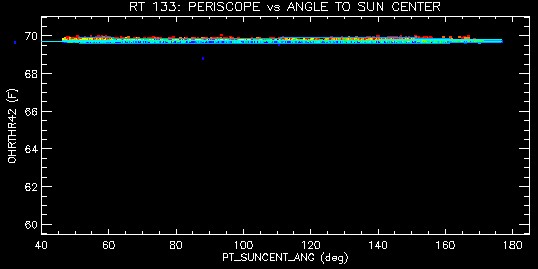

Daily minimum ORTHR42 versus sun pitch angle. Colors indicate time.
http://cxc.harvard.edu/mta_days/mta_deriv/F/ohrthr42_avgPmin.gif
OHRTHR43 RT 134: PERISCOPE
This system has changed by ~0.9° F. We don’t yet understand the implications of that.
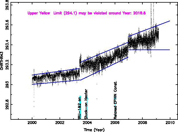
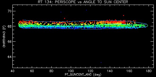

Daily maximum ORTHR43 versus sun pitch angle. Colors indicate time.
http://cxc.harvard.edu/mta_days/mta_deriv/F/ohrthr43_avgPmax.gif
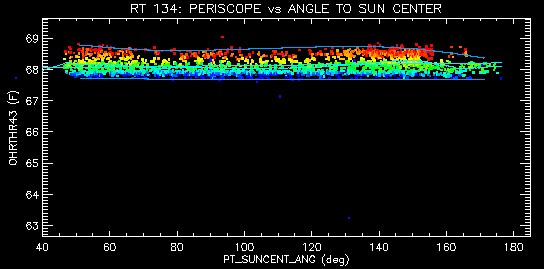

Daily minimum ORTHR43 versus sun pitch angle. Colors indicate time.
http://cxc.harvard.edu/mta_days/mta_deriv/F/ohrthr43_avgPmin.gif
OOBAGRD3 RT 505 TO RT 504: PERISCOPE GRADIENT (°F over some distance)
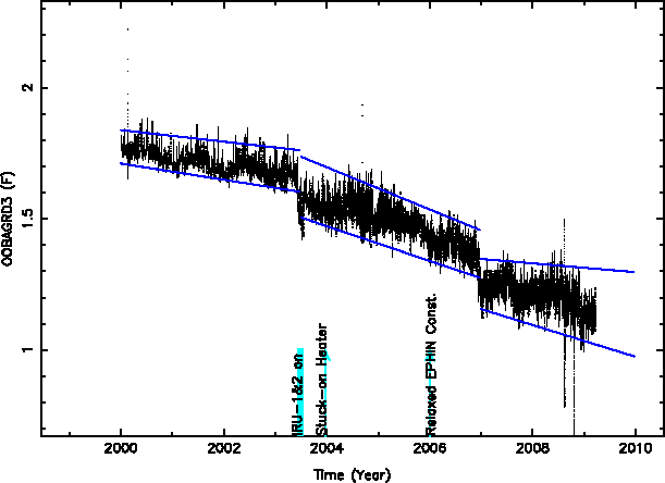
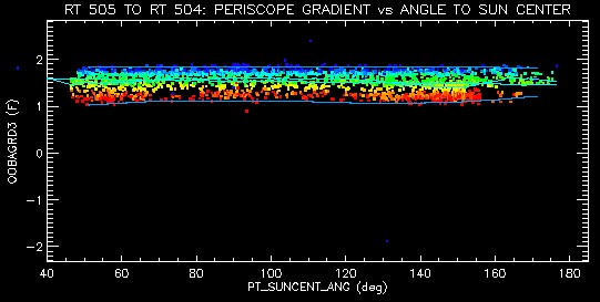

Daily maximum OOBAGRD3 versus sun pitch angle. Colors indicate time.
http://cxc.harvard.edu/mta_days/mta_deriv/F/oobagrd3_avgPmax.gif
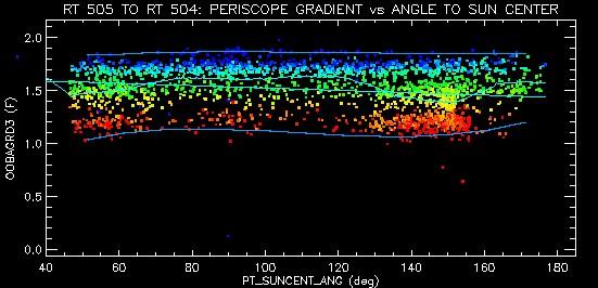

Daily minimum OOBAGRD3 versus sun pitch angle. Colors indicate time.
http://cxc.harvard.edu/mta_days/mta_deriv/F/oobagrd3_avgPmin.gif
OOBAGRD6 RT 507 TO RT 506: PERISCOPE GRADIENT (°F over some distance)
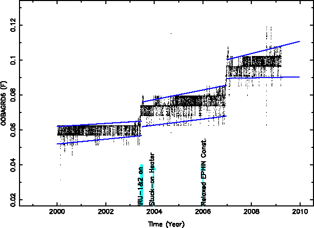
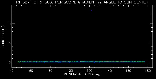

Daily maximum OOBAGRD6 versus sun pitch angle. Colors indicate time.
http://cxc.harvard.edu/mta_days/mta_deriv/F/oobagrd6_avgPmax.gif
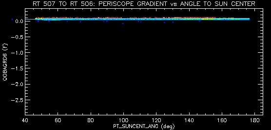

Daily minimum OOBAGRD6 versus sun pitch angle. Colors indicate time.
http://cxc.harvard.edu/mta_days/mta_deriv/F/oobagrd6_avgPmin.gif
MSID yel_lo yel_hi red_lo red_hi Units
TOOBAGRD3 -2.5 2.502 -2.9 2.79 °F
OOBAGRD6 -0.49 0.486 -2.5 2.502 °F
OHRTHR27 73.67 76.73 44.69 94.73 °F
OHRTHR42 67.73 71.69 44.69 94.73 °F
OHRTHR43 66.65 69.71 44.69 94.73 °F
None of the periscope readings have exceeded their yellow or red limits.
Thermal distortions of the periscope could cause a drift in the telescope boresight.
There doesn't seem to be any need to increase the limits on this system at this time, since it is staying well within its limits.
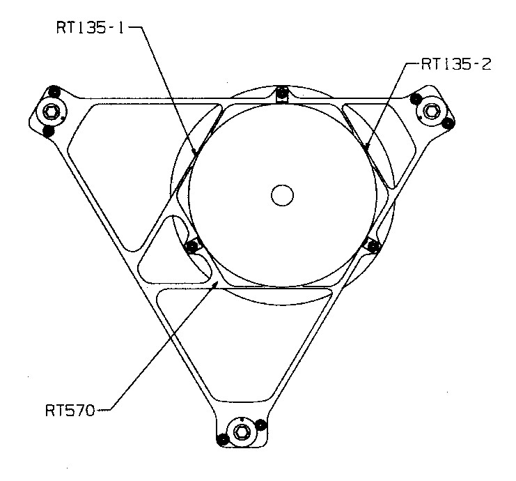
This assembly views the focal plane fiducial lights, collimates a beam of light from them, and reflects it exactly 180°, then shines it on the periscope. From there the beam is transported laterally by the periscope and illuminates the aspect camera.
The RRCA is located in the center of the HRMA. The mnemonics are:
|
Thermistor |
MSID |
|
RT135 |
OHRTHR20 |
|
RT570 |
4RT570T |
The FTM Shield is located on the outboard end of the FTS periscope.
