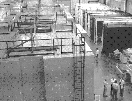
The mirror element fabrication is a major activity being performed at Hughes Danbury Optical Systems, Inc. (HDOS) in Danbury, CT (Fig. 3). The process is fairly conventional, but complicated by the tight tolerances and the flexibility of the elements. The typical process cycle consists of metrology to determine the current shape of the glass, data analysis, run planning, and corrective material removal. The final cycle is followed by acceptance metrology, which also is used to optimize the initial alignment and for performance prediction.
The major instruments used during metrology are the CIDS (circularity and inner diameter station) and the PMS (precision metrology station). The CIDS, as its name implies, is used to determine circularity and the inner diameters. The PMS is used to measure along a meridian; thus, between the two instruments we essentially measure both the `hoops' and `staves' of the barrel, and can map the entire surface.

Figure 3. Mirror fabrication room at Hughes Danbury Optical Systems, Inc. The Precision Metrology Station is housed in the enclosure in the foreground. [Photo courtesy of Hughes Danbury Optical Systems, Inc]
The CIDS detectors are air bearing supported, inductively loaded
probes; two opposing probes are carried on each of two arms which are
located near the top and bottom of the glass, thus making simultaneous
measurements 180 apart at both stations. One end of a probe is
a small sphere which makes contact with the glass, and the other end
is a mirror normal to the probe axis. The separation between a fixed
optical reference cube and the mirror on the back of the probe is
measured with a laser interferometer. This entire assembly then is
rotated on a precision air bearing to determine the circularity at
axial stations near the edges. The opposing probes provide the data
required to correct for errors in the bearing. The inner diameters are
measured by retracting the probes and then moving the arms axially so
that calibrated Zerodur reference bars can be measured. Checks against
systematic errors include reversing the glass top to bottom so that
the measurement of the difference in radii, or equivalently the
average axial slope, will be insensitive to errors in the calibration
of the reference bars; fortunately, we are not very sensitive to
errors in the absolute diameters. The glass also is rotated on the
CIDS so that any errors azimuthally fixed with the instrument can be
detected and compensated. The elapsed time for a set of CIDS
measurements is about three days, depending on whether or not the
glass is inverted, etc.
The PMS is used to measure interferometrically the separation between a carefully calibrated reference cylinder (which is called a toroid for historical reasons). One azimuthal position is measured a number of times, typically 10, but as many as 40 for final acceptance. The mirror element then is rotated azimuthally and the process repeated. Typically 144, 288, or 576 meridians are measured, depending upon the stage of the polishing process. Two types of tests for systematic errors are performed. The element can be displaced axially by small amounts, resulting in sensitivity to errors higher than second order as long as they are not periodic with a period equal to an integral divisor of the displacement; this is called a shear test, and can be performed with an accuracy comparable to the tolerances. The mirror also can be inverted, providing sensitivity to errors which are odd functions of the axial coordinate. These two types of check provide sanity measurements for all PMS parameters except for the sagittal depth, or `axial sag'. The sanity checks for axial sag include varying the axial stations measured with the CIDS, and making a direct comparison with two lower resolution mechanical profilometers which are used in the earlier stages of the fabrication process; the accuracies of these cross checks are comparable to the requirements. The elapsed time for a set of PMS measurements is about four days, again depending upon how extensive a data set is required.
The mirror must be supported carefully during CIDS and PMS measurements; this is accomplished using the precision metrology mount (PMM). The mirrors typically are supported at three `hard' points, which determine position kinematically, and 15 `soft' points, in which a measured support force is applied, but position is not constrained. Tolerances on these off loading forces are of order 0.01 pounds, which may be compared to the approximately 500 pounds weight of the largest mirror elements. The PMM introduces distortions which must be calculated and removed from the data. The support induced distortions have scale lengths short compared to the length of the optical elements, and so the accuracy of the calculations can be verified by demanding consistency between data taken with the mirror in its normal and inverted orientations. This also provides a check on the PMM support force tolerance analysis.
Finally, after the last cycles, the microroughness is sampled using a slightly modified WYKO Corporation instrument on a mount which allows access to the inside of the optical elements.
The data analysis and run planning activity consists of reducing the data to determine the surface errors followed by tool selection to optimize the reduction of these errors. A run tape for each tool is generated; this essentially adjusts the local dwell times so that the convolution of the tool path and dwell times with the selected tool removal profile is proportional to the local errors. Typically of order 600 megabytes of raw data are processed for each polishing cycle of each element.
----------------