
|
|
|
Beginning with Cycle 24 (fall 2022), the default ACIS dither increased from 16" to 32" (full width). In order to maintain the margin between the aimpoint and the nearest chip node boundary, the ACIS-S aimpoint likewise shifted by 8" from (CHIPX,CHIPY)=210,520 to (CHIPX,CHIPY)=194,520. Information on this page, particularly the choice of Y-offset, has been updated accordingly.
This page is intended to aid proposers and observers as they select instrumental parameters for LETG/ACIS-S observations, specifically with regard to pointing offsets and subarray configurations. Most of the information presented here is also in the Proposer's Observatory Guide (see especially Table 9.3 and section 9.4.2/Offset Pointing). The additional contributions of this page are specific subarray configurations and links to the Spectrum Visualization Tool.
The default for the SIM Offset is 0 in order to maximize effective area at energies below ~1 keV. With this SIM Offset value the spectrum will fall near the middle of the CCD array, around row CHIPY=520, where contaminant on the ACIS UV/Ion Shield is thinnest.
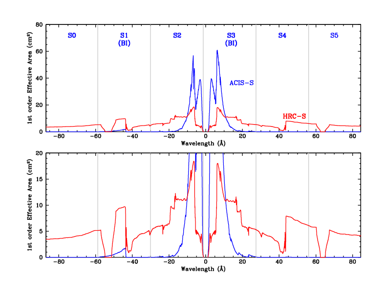
Most LETG/ACIS-S observations are offset in Y in order to place the important He-like O lines and the O-K absorption edge on the S3 chip, away from the S4 chip. As seen in the figure below, the Backside-Illuminated (BI) chips, S1 and S3, have much higher QE at low energies than the Front-Illuminated (FI) chips.
As of Cycle 24 (with its changes in dither and aimpoint), the current recommendation for most LETG/ACIS observations is to use Yoffset=1.07', which will place the major Oxygen features on S3 while ensuring that 0th order does not get too close to the S2/S3 gap.
The Spectrum Visualization Tool displays where spectral features fall on the ACIS-S detector as a function of Y-offset and source redshift. Positions are only approximate, however, because of aimpoint scatter, which can be up to ±11" (0.18') in Y (along CHIPX). One arcminute of Y-offset corresponds to a shift of 3.36 Å. When choosing an offset, observers should keep several margins in mind:
|
| Figure 1: LETGS 1st order effective area (EA) with ACIS-S and HRC-S; lower panel shows low-EA regions in more detail. The effects of dither and ACIS bad columns are included. Light grey lines mark ACIS chip boundaries, and HRC plate gaps appear near -53 and +63 Å. ACIS curve is for Y-offset=+1.07' and HRC curve is for Y-offset=0'. ACIS EA is from July 2024. |
Very few LETG/ACIS observations use the full ACIS-S array, which has 1024 rows and takes 3.2 seconds to read out. Using a subarray and/or fewer chips allows a faster readout (shorter frametime) and thus produces less pileup in 0th order and the dispersed spectrum.
From Figure 1 one can see that S0, S4, and S5 are useless for detecting 1st-order photons, although they may be useful for collecting higher order spectra in some cases. Because of increasingly stringent ACIS thermal requirements, the S0, S4, and S5 chips should be turned off unless there is a good reason for their use. Note that chips can be marked as "Optional", in which case they will be only be turned on if Mission Planning schedulers determine that thermal constraints will not be violated.
The LETG/ACIS background is weak enough that observers often don't bother with background subtraction. In this case, a subarray as small as 128 rows can be used. If background subtraction is to be used, a subarray of at least 192 pixels is needed; 88 pixels for the default background regions which extend to 1.06 mm on either side of the spectrum, 64 pixels (32") for dithering, and 40 pixels for Z pointing errors of up to ±10". Alternatively, users may reprocess their data by specifying narrower background regions in tg_extract.
To summarize, 3 or 4 chips will suffice for most observers.
A 128-row subarray should be OK but there will be little room
for background regions. If you plan to use
the standard background regions you should chose at least 192 rows,
although custom background regions can be specified to use
whatever area is available.
The tables below list subarray parameters for the
traditional 1/2, 1/4, and 1/8 subarrays,
and for optimized subarrays that maximize the
number of rows for a given frametime.
SIM Offset=0 and Z-Offset=0 are assumed, with
the spectrum centered in the cross-dispersion direction
on row 520 (very near the center of the ACIS-S array).
| CCDs | 3 chips | 4 chips | ||||||||
|---|---|---|---|---|---|---|---|---|---|---|
| Rows | 303 | 267 | 232 | 196 | 160 | 283 | 247 | 211 | 175 | 139 |
| Start | 368 | 386 | 404 | 422 | 440 | 378 | 396 | 414 | 432 | 450 |
| FrameTime | 1.0 | 0.9 | 0.8 | 0.7 | 0.6 | 1.0 | 0.9 | 0.8 | 0.7 | 0.6 |
| CCDs | 5 chips | 6 chips | ||||||
|---|---|---|---|---|---|---|---|---|
| Rows | 263 | 226 | 190 | 153 | 242 | 205 | 169 | 132 |
| Start | 388 | 407 | 425 | 443 | 399 | 417 | 435 | 454 |
| FrameTime | 1.0 | 0.9 | 0.8 | 0.7 | 1.0 | 0.9 | 0.8 | 0.7 |
| CCDs | 3 chips | 4 chips | 5 chips | 6 chips | ||||||||
|---|---|---|---|---|---|---|---|---|---|---|---|---|
| Subarray | ½ | ¼ | ⅛ | ½ | ¼ | ⅛ | ½ | ¼ | ⅛ | ½ | ¼ | ⅛ |
| FrameTime | 1.6 | 0.9 | 0.6 | 1.7 | 1.0 | 0.6 | 1.7 | 1.0 | 0.7 | 1.8 | 1.1 | 0.7 |
Frametime for m active CCDs, using n rows starting with row q, is given by the equation
T(msec) = 41.12*m + 2.85*n + 0.040*m*q - 32.99
and rounding up to the nearest 0.1 sec.
Last modified: 10/04/24
|
The Chandra X-Ray
Center (CXC) is operated for NASA by the Smithsonian Astrophysical Observatory. 60 Garden Street, Cambridge, MA 02138 USA. Email: cxcweb@head.cfa.harvard.edu Smithsonian Institution, Copyright © 1998-2004. All rights reserved. |