 |
 |
 |
|
Image 13 of 13 |
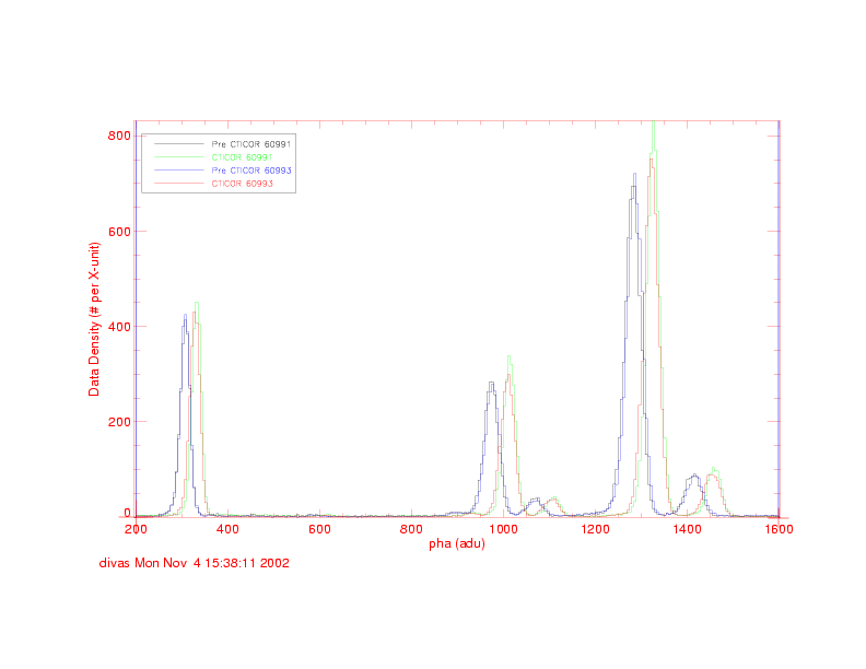
We apply CTI corrector to the S3 data using the values of CHIPY in the event list. For TE data, we go from pre-CTICOR (black line) to CTI corrected (green line). In TE mode, since we know both CHIPX and CHIPY positions for each event, the CTI corrected spectrum is what would be expected.
For CC mode data, we go for pre-CTICOR (blue line) to CTI corrected (red line). Again an improvement.
Comparing the CTI corrected TE spectrum (green line) and the CC spectrum (red line), we can conclude that the CTI correction on S3 data in CC mode does a good job. I believe this is because most of the CTI on S3 is serial CTI and the CTI corrector accounts for that as we know the CHIPX positions of all events in CC mode (serial CTI depends on CHIPX position). There is some parallel CTI which CTI corrector does not fully correct as the spectrum was integrated over the full range of CHIPY.
I believe that for a point source observed on S3 in CC mode (where we can calculate the point source position along CHIPY from the aspect solution) and use that CHIPY value for CTI correction, the PSU CTI corrector would do a good job at mitigating the effects of CTI and I would strongly recommend the scientist to do so.
Also the CXC calibration group should plan to do some tests to verify or reject this hypothesis about CTI correction of the CC mode data observed on BI chips.
Note: Preliminary test on S1 data in CC and TE mode give results similar to those obtained for S3.
Regarding the CC mode observations on FI chips, I feel that the CTI corrector might work if we use the expected source position, but I am not sure of that.