
|
|
|
Martin Weisskopf and Allyn Tennant have been analyzing LETG/HRC-S spectra from the Crab pulsar hoping to measure the temperature or put an upper limit on thermal emission (which probably peaks longward of 20 Å) from the surface of the neutron star. Because the extremely bright non-thermal power-law emission from the nebula and pulsar, together with any thermal signal, is heavily absorbed at low energies, most of the dispersed events at mλ > 20 Å are from higher orders of shorter wavelengths. Attempting to tease out any thermal emission in this range requires a more accurate calibration of LETG higher-order diffraction efficiencies than provided by the current (2004, slightly updated in 2010) calibration contained in the N0006 version of the LETG Grating Efficiency (GREFF) file in the CALDB. Orders m=4, 5, 6 are particularly important and Weisskopf/Tennant provided evidence that the CALDB efficiencies for those orders might be too high, especially around mλ ∼ 50 Å.
Using LETG/ACIS-S spectra from 6 observations of bright continuum sources, relative grating efficiencies (normalized to 1st order) were measured for m = 2 to 10 for mλ < 80 Å. In the worst case, near 12 Å, measured efficiencies were consistently found to be 15-20% smaller than the N0006 GREFFs for orders m = 3-6, with all orders' efficiencies at least slightly smaller than the model over most of the measured wavelength range, with some exceptions for 2nd and 3rd order. Calibration uncertainties short of ∼6 Å are greater than 10% (perhaps 20%?) because of a paucity of counts and systematic uncertainties in the large pile-up corrections, but uncertainties (relative to 1st order) for the new GREFFs (N0007) are estimated to be 5-10% (best for 3rd order and generally increasing with larger m) over the calibration range. Errors are unknown but presumably larger for mλ > roughly 80 Å and for orders beyond m=10. Summary plots are shown below, and again at the end with more explanation.
|
|
|
|
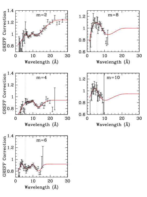
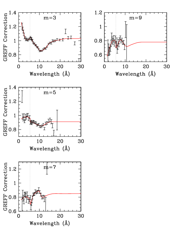
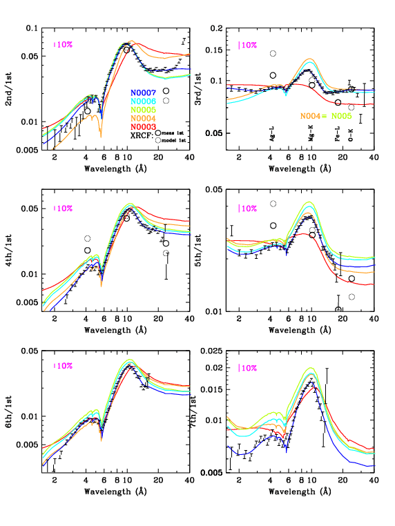
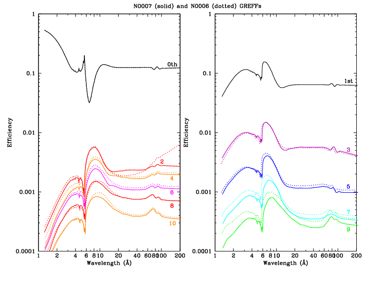
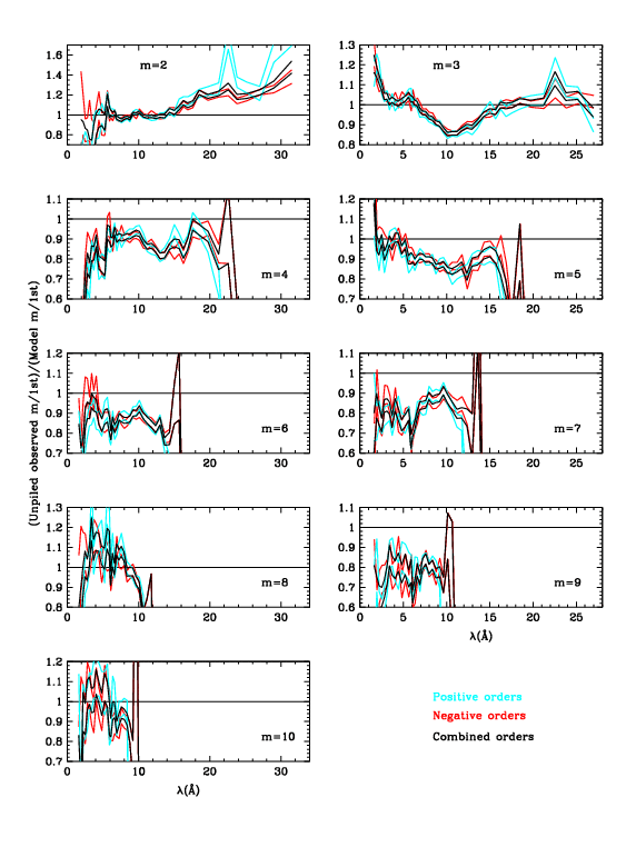
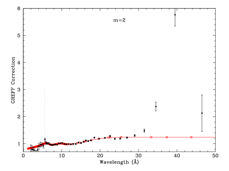
| Figure 1 (ps, pdf): Even orders, showing measured m/1st divided by GREFF m/1st. Here (gif, ps, pdf) is a version of the 2nd order plot that goes out to 50 Å; red circles indicate energy points in the GREFF file. | Figure 2 (ps, pdf): Odd orders. The dotted vertical lines at 5.519 Å (2.247 keV) mark the Au-MV edge, where grating efficiencies change abruptly (see Figs. 3 and 4). | Figure 3 (ps, pdf): Orders 2-7, comparing measured and GREFF m/1st. XRCF results are also shown (see 3rd order panel for labels), although their uncertainties may be large. (Yes, the errorbars appear distorted but they print OK.) | Figure 4 (ps, pdf): Comparison of grating efficiencies from version N0006 and N0007. For clarity, even orders are on the left and odd orders on the right. The rise in the N0006 2nd order at long wavelengths, which dates to version N0004, was judged to be unphysical; beyond 30 Å, 2nd order is set to a constant multiple of 4th order. |
N0003 was the version at launch, based on subassembly calibration and analysis of XRCF data. Further analysis of XRCF and Panter ground-calibration data led to modifications of 2nd and 3rd order in version N0004 (Jan 2001). Analysis of on-orbit LETG/ACIS data for m=2-7 generated version N0005 (Aug 2004); subsequent recognition of a systematic error caused by the spectral extraction region used in that analysis led to small reductions in the efficiencies of those same orders (2-9%, with the larger corrections for larger m) in N0006 (Apr 2010; see bottom of this page).
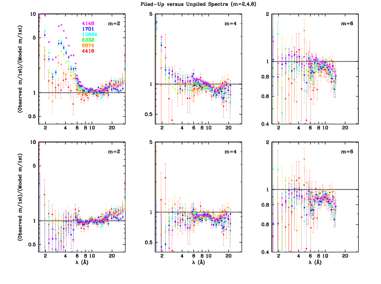
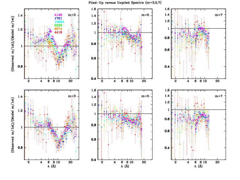
Since higher orders are so weak, the primary criterion when choosing observations for this analysis was the total number of counts, i.e., we desired high source intensity and long exposure times. Ideally, all the observations would be made with the same pointing offsets (default Yoffset=+1.5' and Zoffset=0) and SIMZ (-8 mm) so that they would have the same line spread function in the cross-dispersion direction and therefore the same pile-up parameters. ObsID 1701 had a different Yoffset but its data were too valuable not to use (see Figs. 5 and 6). ObsID 5332 had SIMZ=0 and so its spectrum fell on a different strip of ACIS from the others (a shift of 333 rows) but no evidence for different pile-up parameters was seen. Six ObsIDs were chosen for analysis, with rates that varied over roughly a factor of 20.
|
|
|
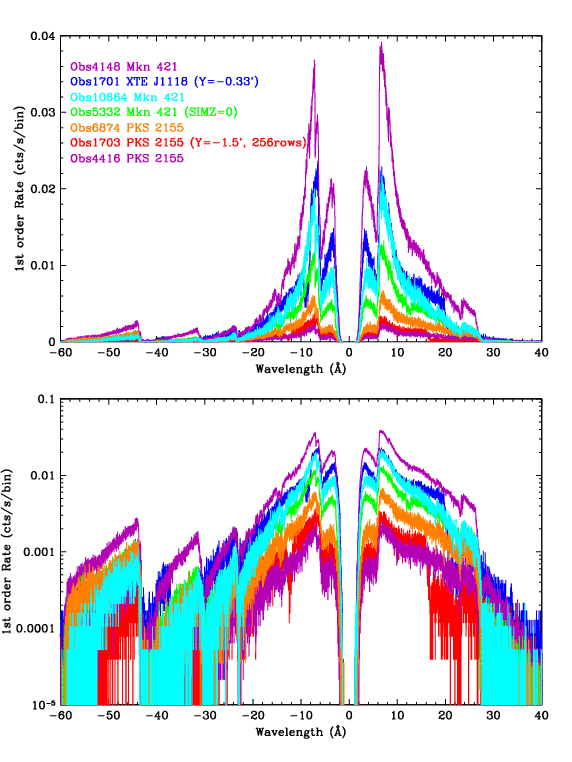
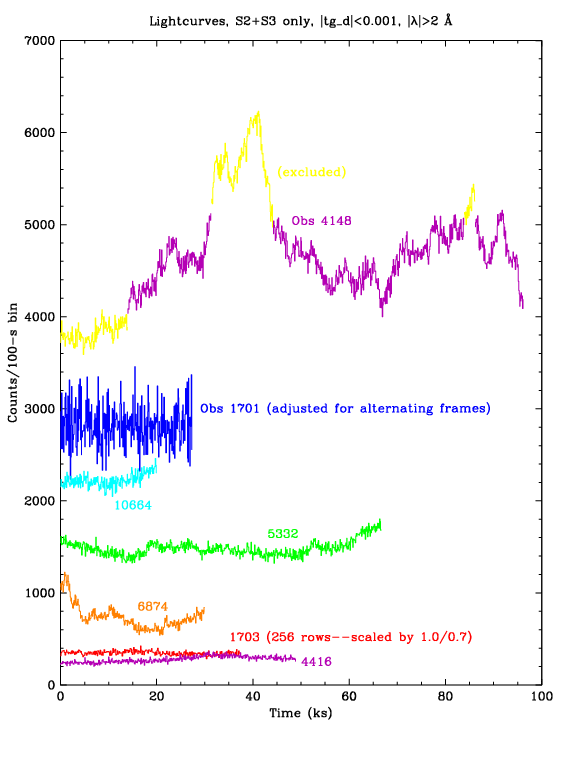
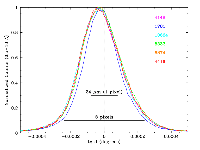
| Figure 5 (ps, pdf): Spectra of 7 ObsIDs, with default 0.0125-Å binning. ObsID 1701 used Yoffset=-0.33' instead of the standard +1.5' and required special tuning of its pile-up parameters because its spectrum was more tightly focused in the cross-dispersion direction (see Fig. 7). ObsID 1703 used Yoffset=-1.5', and should have the same line spread function as the +1.5' data, but was not used in the final analysis because it contained even fewer counts than the already marginal Obsid 4416. | Figure 6 (ps, pdf): Spectrum light curves with 100-sec binning. Background data were also studied to remove a few periods of background flaring. Low- and high-source-rate periods of ObsID 4148 were excluded from the analysis in order to minimize nonlinearities in the pile-up corrections. ObsID 1701 used alternating-frame exposures (0.1 and 0.7 sec); only the 0.7-sec data were used, and the rates shown here have been multiplied by 1.103 to illustrate the event rate per frame (which is the relevant rate for pile-up calculations). Similarly, rates for ObsID 1703 were multiplied by 1.0/0.7 to account for its 1.0-sec frame time (using 256 rows instead of the 128 rows for all other ObsIDs). | Figure 7 (ps, pdf): Cross-dispersion distributions. The profiles of the 5 ObsIDs made at Yoffset=+1.5' are virtually the same, while the distribution for ObsID 1701 (Yoffset=-0.33') is significantly narrower, requiring larger pile-up parameters. |
Data were reprocessed to Level 2 using the new LETG/ACIS tilt correction. All the data had severe pile-up in 0th order and downstream results at the shortest wavelengths were found to be extremely sensitive to the position of 0th order--shifts of 0.1 pixel had a significant effect--so 0th order was determined manually. This was done by excluding a 10-pixel-radius core and then maximizing the number of counts within 2- or 3-pixel-wide extraction regions by varying angle and position along the dispersion and cross-dispersion axes in an interative process. The improved 0th order coordinates were used in tg_create_mask and tgextract extracted plus and minus orders of m=1-10.
A rectangular extraction region was used so that all orders at a given wavelength have the same extraction efficiency, apart from astigmatism (see POG figures 9.14 and 9.15) at large mλ. Astigmatism is a function of dispersion, i.e., it depends on mλ rather than wavelength λ; 5th order of 16 Å is signficantly broader in cross-dispersion than 1st order of 16 Å. A relatively wide region of |tg_d| < 0.0015 degrees was used to keep the difference in extraction efficiency between different orders below ∼1%.
Raw spectra (COUNTS, BACKGROUND_UP, and BACKGROUND_DOWN) were taken from pha2.fits files and net model effective areas (SPECRESP) were taken from garf.fits files. The SPECRESP column is equal to QE*AREA*FRACEXPO*OSIP where QE is ACIS quantum efficiency, AREA is HRMA effective area times grating efficiency (for each order), FRACEXPO is the effective exposure fraction accounting for dithering across missing columns and chip gaps, and OSIP is the Order Sorting Integrated Probability within the energy range appropriate for the given order and wavelength. OSIP values are very close to 1.0; only a small fraction of events falls below or above the energy range of interest (ROI) for each order. In reality, the effective OSIP for orders with m>1 will on average be 100% because any m-order events that fall outside the ROI will be compensated by m-1 and m+1 events that fall inside the m-order ROI, but the difference from the CALDB OSIP is assumed to be negligible.
Note that when fitting spectra to derive source fluxes, the model spectrum is equal to the incident source spectrum times the Exposure times SPECRESP times the Encircled Energy Fraction (EEFRAC). EEFRACs are interpolated from tabulated values in the LSFPARMs file, which was recently updated for the LETG/ACIS in CALDB 4.4.1 (Dec 2010). EEFRACs are not used in the present analysis because the spectral extraction region has been chosen so that EEFRACs from different orders are the same and cancel out.
Background data were taken from the outer edges of the spectral region to the edges of the 128-row subarray (126 rows after 3x3-pixel event grading) for each observation, giving a BG/spectrum area ratio (BACKSCAL) of 5.682. (BACKSCAL would be 9.0 for ObsID 1703--with its 256-row subarray--using an outer BG limit of |tg_d| < 0.0150.) Background-subtracted rates were computed for each order in units of cts/frame/pixel (with distance in pixels measured along the dispersion axis) for each of 50 wavelength bins (for both + and - orders) in tg_mlam (mλ), with narrower bins in higher-count regions of the spectrum.
ACIS pile-up occurs when two or more events spatially interact within a single exposure frame and are then treated as a single event. (Note that in the following discussion we use somewhat different nomenclature than in the Proposers' Observatory Guide.) If that "single" event has a valid grade it is treated as having the summed energy of its two component events and we call it "true" pileup. If it has an invalid grade we call it "grade-migration" pileup and the event is lost.
A physically based pile-up model would consider each event's charge distribution within the relevant 3x3-pixel island. Such a complex approach is impractical and instead we assume that pile-up can be approximated using only the 1-dimensional event rate of the dispersed spectrum after collapsing it in the cross-dispersion direction, effectively giving us a 3x1-pixel spatial element. (In fact, a 1x1-pixel approach gives almost identical results but we use the 3x1 method here.) Event rates--determined for each observation and order in tg_mlam bins as described above--are used in combination with pile-up parameters kp (for true pile-up) and kg (for grade-migration pile-up) to compute Poisson probabilities of having 0, 1, and 2 events of each kind (p or g) within the central and adjacent pixels (i.e., collapsed columns). It is assumed that the probability ratio for true vs grade-migration pile-up is the same in all three columns and that the summed probability in the central column is 1 (not quite true because the cross-dispersion profile extends more than 3 pixels, but this is largely compensated for when tuning the pile-up parameters). The equations giving observed event rates (after true pile-up and grade-migration losses) are more concisely written in terms of kp and ktot (where ktot = kp +kg) and are given here.
Pile-up parameters are different for Back-Illuminated (BI) and Front-Illuminated (FI) ACIS chips so there are 4 free parameters that must be determined. We do this by calculating the ratio of counts from different orders after applying pile-up corrections, and adjusting the pile-up parameters until good agreement is found among results from several ObsIDs with varying degrees of pile-up. Observed events from 2nd order, which has very low efficiency below ∼5.5Å, consist almost entirely of piled-up 1st order events, and so kp can be calibrated by studying the 2nd/1st ratio. Likewise, the 3rd/1st ratio from ∼6-9 Å is the most sensitive test of the value of ktot.
Count ratios (mth order divided by 1st order) are computed by first applying the pile-up corrections determined within each tg_mlam slice to each of the 0.0125/m-Å bins in the observed spectra. (Binning for SPECRESP is the same.) The observed spectra and SPECRESPs for each order are then rebinned in tg_lam space so that mth/1st ratios can be computed. In order to correct for dither across missing columns (which is accounted for by SPECRESP, also referred to as the "model"), the ratios actually used to tune the pile-up parameters and derive final results are [observed(m)/observed(1)]/[model(m)/model(1)]. Statistical errors are computed for the observed spectra and 10% (15% for ObsID 1701) of the net pileup correction is added to each order's error (simple addition, not quadrature) before finally computing the total ratio uncertainty in quadrature.
To avoid biasing results toward high-rate observations (which have the best statistics but also have the most pile-up-distorted order-efficiency ratios) we simply computed the variance among results from the 5 ObsIDs made at Yoffset=+1.5' as pile-up parameters were varied. To obtain independent calibration of each parameter we chose wavelength ranges where 2nd [3rd] and 1st orders both fell on the same chip, S2 (FI) for negative orders and S3 (BI) for positive. There is some interdependence of kp and ktot but the process was iterated and the tuning results are mostly orthogonal. Results, including a discussion of energy dependence in kp and special treatment of ObsID 1701, are described here.
After determining the pile-up parameters, final corrections were applied to all spectra and the error-weighted average ratios for each order (negative, positive, and combined) were computed. Fig. 8 shows the pseudo-1σ boundaries for +, -, and combined ratios. Figs. 9 and 10 show the combined order-efficiency ratios before (top panels) and after (bottom) pile-up corrections.
|
|
|
| Figure 8 (ps, pdf): Error limits for +, -, and combined order-efficiency ratios. There is generally very good agreement between + and - results. The outliers for m=+2 and +3 around 22 Å may indicate a small problem in O-K near-edge structure in the ACIS QE for S2 and/or S3. | Figure 9 (ps, pdf): Even orders (2,4,6) before and after pile-up corrections. | Figure 10: (ps, pdf): Odd orders (3,5,7) before and after pile-up corrections. |
|
|
|
|
|
| Figure 1 (ps, pdf): Even orders, showing measured m/1st divided by GREFF m/1st. Here (gif, ps, pdf) is a version of the 2nd order plot that goes out to 50 Å; red circles indicate energy points in the GREFF file. | Figure 2 (ps, pdf): Odd orders. The dotted vertical lines at 5.519 Å (2.247 keV) mark the Au-MV edge, where grating efficiencies change abruptly (see Figs. 3 and 4). | Figure 3 (ps, pdf): Orders 2-7, comparing measured and GREFF m/1st. XRCF results are also shown (see 3rd order panel for labels), although their uncertainties may be large (see below). (Yes, the errorbars appear distorted but they print OK.) | Figure 4 (ps, pdf): Comparison of grating efficiencies from version N0006 and N0007. For clarity, even orders are on the left and odd orders on the right. The rise in the N0006 2nd order at long wavelengths, which dates to version N0004, was judged to be unphysical; beyond 30 Å, 2nd order is set to a constant multiple of 4th order. |
N0003 was the last set of GREFFs based on an analytical grating model, as opposed to the ad hoc/empirical corrections of later versions, and so we judged it to be the best theoretical guide to how grating efficiencies should behave at wavelengths beyond the LETG/ACIS useful range (roughly mλ > 70 Å). The grating bars are effectively opaque beyond ∼30 Å, apart from some Au edge structure around 80 Å, and so grating efficiency should be constant. The rise in 2nd order efficiency beyond 30 Å, which was introduced in N0004, is therefore nonphysical and we set 2nd order to be a constant multiple of 4th order efficiency beyond that point (see Fig. 4).
We likewise expect all the non-0 even orders to have a roughly similar shape, which is different from odd-order behavior. The clear dips around 13 Å seen in 2nd and 4th order in Fig. 1 are therefore expected to have analogs in 6th, 8th, and 10th order, so the GREFF Correction factors were drawn to approach an intermediate value at longer wavelengths, even though we have no observational data to support that. A similar dip is seen in 3rd and 5th order around 11 Å, and we again extrapolate the curves to approach intermediate values at longer wavelengths. Given the abrupt changes in grating efficiencies at the Au-MV edge (5.519 Å; Figs. 3 and 4), one might expect similar changes in the order-efficiency ratios. We therefore assumed that the jumps/slope changes seen in all the odd orders of Fig. 2 are real, and did not try to smooth them. At the shortest wavelengths, where statistics are poor and pile-up corrections are often large, we erred on the side of not departing too far from a correction factor of 1. Uncertainties short of the Au-M edge are large, but of very little practical importance.
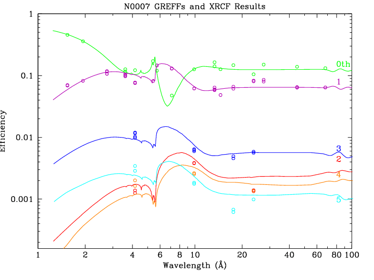
Fig. 3 includes all available results for pre-flight XRCF calibration of higher orders. Thick circles denote ratios using the XRCF-measured 1st order efficiency while thin circles denote normalization to the GREFF ("model") 1st order. The points near 4 Å are from Ag-L, which has a complex line and absorption-edge structure resulting in large systematic uncertainties. Systematic uncertainties for the Fe-L points near 17.5 Å (for 3rd and 5th order) should be smaller. Errors for Mg-K (10 Å) and O-K (24 Å), which have relatively simple emission-line and filter-absorption spectra, should be even smaller but the difference between the model and observed 1st order efficiency for O-K is obviously quite large. Because the XRCF calibration for higher orders (see Fig. 11) has such sparse wavelength coverage and its uncertainties are larger than those in the present work we did not give the XRCF results any weight in deriving our final results.
|
| Figure 11 (ps, pdf): XRCF calibration results for the LETG. |
The general trend of the 3rd order corrections seen here matches what was seen less clearly in the 2004 N0005 analysis; no adjustment was made then because the corrections were relatively small compared to those required for other orders and because of doubts about the physical reality of the apparent deviations over such small wavelength ranges. With more observational data, better statistics, and other improvements in the present work, the deviations between observation and model are now clear. It is not clear, however, why all the even [odd] order corrections (Fig. 1 [Fig. 2]) have dips near 13 [11] Å. One likely contributing factor, however, is that the ktot pile-up coefficients determined in the present work are roughly 50% larger than those found in 2004 (see detailed discussion of pile-up parameter tuning). The common feature of GREFF correction factors being smaller than 1 for m=4-7 is probably due to deficiencies in background subtraction in the 2004 analysis, which made the diffraction efficiencies seem larger than they were. This is particularly noticeable for m=7, which is the weakest of the orders studied in 2004.
The relative increase in GREFF for m=2 longward of ∼15 Å (Fig. 1) was seen in the 2004 analysis but not believed because of concerns over uncertainties in the ACIS calibration of the outer CCDs at such long wavelengths and because such an increase was not seen in 4th order. The present work shows that the increase is indeed real out to ∼30 Å, although probably not beyond that for the reasons noted in the previous section.
It is unlikely that more than a few LETG observers will notice a statistically significant change in their analysis results using these new higher order efficiencies. LETG/ACIS spectra, which have order separation, should show small improvements in agreement between 1st and higher orders; 1st order fits will of course remain unchanged. More practical benefit is found for LETG/HRC spectra, which do not have enough detector energy resolution to separate orders. Strong features in line-dominated spectra will be negligibly affected, but weaker 1st order lines that blend with higher orders of stronger lines might yield significantly different fit results. For most of these weaker lines, however, statistical uncertainties, detector background, pseudo-continuum (unknown and unresolved lines), wavelength errors (multiplied by m for higher orders), and possible HRC-S distortions in line shapes and positions are likely to be larger factors than changes caused by the new higher order efficiencies.
One clear situation in which the new GREFFs will make a significant difference is when studying hard, bright spectra in a wavelength range where the 1st order spectrum is dominated by higher orders because of low-energy cutoff from interstellar absorption (for example, the Crab analysis that motivated the present work). In such situations, uncertainties in the HRC-S QE, which are larger for higher orders than for 1st order, must also be considered.
Last modified: 04/20/11
|
The Chandra X-Ray
Center (CXC) is operated for NASA by the Smithsonian Astrophysical Observatory. 60 Garden Street, Cambridge, MA 02138 USA. Email: cxcweb@head.cfa.harvard.edu Smithsonian Institution, Copyright © 1998-2004. All rights reserved. |